Hyundai Tucson: Cylinder Block / Crankshaft

ŌĆó Be careful not to damage the parts located under the vehicle (floor under cover, fuel filter, fuel tank and canister) when raising the vehicle using the lift.(Refer to General Information - "Lift and Support Points")

ŌĆó Use fender covers to avoid damaging painted surfaces.
ŌĆó Wait until the engine cools down to room temperature to avoid damaging the cylinder head before removing.
ŌĆó When handling the metal gasket, be careful not to fold or damage the surface.
ŌĆó To avoid damage, disconnect the wiring connectors carefully.

ŌĆó Mark all wirings and hoses to avoid misconnection.
ŌĆó Turn the crankshaft pulley so that the piston of No.1 cylinder is positioned at the Top Dead Center (TDC).
1.Remove the engine and transaxle assembly from a vehicle.(Refer to the Engine And Transaxle Assembly - "Engine And Transaxle Assembly")
2.Remove the automatic transaxle.(Refer to the Automatic Transaxle System - "Automatic Transaxle")
3.Remove the drive plate.(Refer to Cylinder Block - "Drive Plate")
4.Remove the rear oil seal. (Refer to the Cylinder Block - "Rear Oil Seal")
5.Install the engine to engine stand for disassembly.
6.Remove the cylinder head cover. (Refer to the Cylinder Head Assembly - "Cylinder Head Cover")
7.Remove the oil pan.(Refer to the Lubrication System - "Oil Pan")
8.Remove the timing chain cover.(Refer to the Timing System - ŌĆ£Timing Chain CoverŌĆØ)
9.Remove the timing chain.(Refer to the Timing System - ŌĆ£Timing ChainŌĆØ)
10.Remove the Integrated Thermal management Module (ITM).(Refer to the Cooling System - "Integrated Thermal management Module (ITM)")
11.Remove the intake/exhaust/CVVT and camshaft assembly.(Refer to the Cylinder Head Assembly - "CVVT & Camshaft")
12.Remove the intake manifold.(Refer to the Intake And Exhaust System - "Intake Manifold")
13.Remove the exhaust manifold.(Refer to the Intake And Exhaust System - "Exhaust Manifold")
14.Remove the EGR cooler.(Refer to the Intake And Exhaust System - "EGR cooler")
15.Remove the EGR control valve.(Refer to Engine Control / Fuel System - "EGR Control Valve")
16.Remove the cylinder head.(Refer to the Cylinder Head Assembly - "Cylinder Head")
17.Remove the oil pump.(Refer to the Lubrication System - "Oil Pump")
18.Remove the balance shaft assembly.(Refer to the Lubrication System - "Balance Shaft Assembly")
19.Remove the water pump.(Refer to the Cooling System - "Water Pump")
20.Remove the alternator.(Refer to the Engine Electrical System - "Alternator")
21.Refer to the oil filter & oil cooler.(Refer to the Lubrication System - "Oil Filter & Oil Cooler")
22.Remove the lower crankcase.
(1)Loosen the lower crankcase mounting bolts.
(2)Loosen the crankshaft bearing cap bolts.
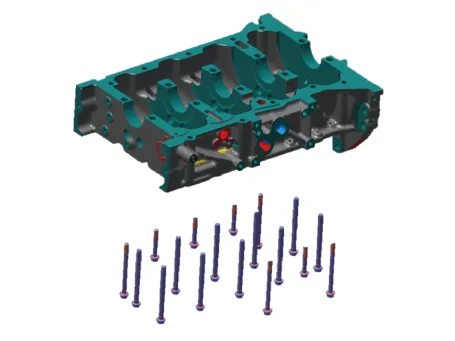
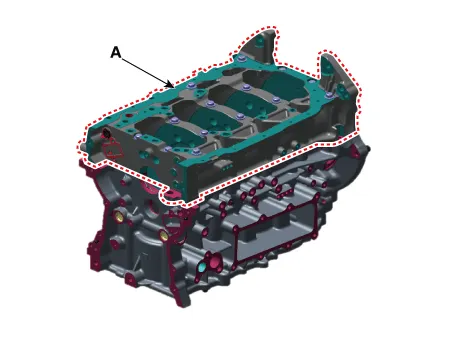
(3)Remove the lower crankcase (A).
23.Remove the piston and connecting rod assembly.(Refer to the Cylinder Block - "Piston and Connecting Rod")
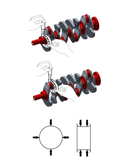
24.Remove the crankshaft (A) from the cylinder block. At this time, be careful not to damage the crankshaft journals.
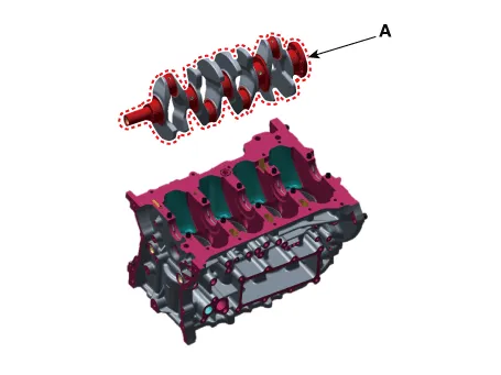

ŌĆó Arrange the main bearings and thrust bearings in regular sequence.
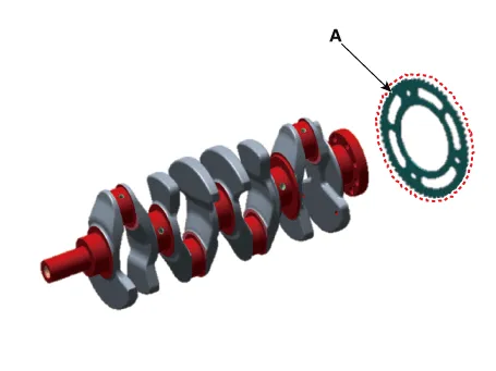
25.Remove the crankshaft position sensor wheel (A).

1.Measure the oil clearance of crankshaft bearing.
(1)Clean each main journal and bearing with a cloth, etc.
(2)Place a piece of plastic gauge in the axial direction of each main journal.
(3)Refit the bearing and bearing cap and then tighten to the specified torque.
Tightening torque : Crank lower case mounting bolts : 29.4 - 33.3 N.m (3.0 - 3.4 kgf.m, 21.7 - 24.6 Ib-ft)Bearing cap mounting bolts : 27.5 - 31.4 N.m (2.8 - 3.2 kgf.m, 20.3 - 23.1 lb-ft) + 120 - 125┬░

ŌĆó Do not turn the crankshaft.
(4)Remove the lower crankcase and then measure the widest part of the plastic gauge.
Bearing oil clearance : #1, 2, 4, 5: 0.022 - 0.040 mm (0.00087 - 0.00157 in.) #3: 0.028 - 0.046 mm (0.00110 - 0.00181 in.)
(5)If the measured value of the plastic gauge is out of the specified value, replace bearing with a new one having the same classification color and then remeasure the oil clearance. (Refer to the crankshaft bearing selection table)

ŌĆó Do not adjust the clearance by machining the bearing or cap.
(6)If the remeasured value is still out the specified value, install the next larger or smaller bearing and then remeasure the oil clearance. (Refer to the crankshaft bearing selection table)

ŌĆó If the remeasured value is still out the specified value, install the next larger or smaller bearing and then remeasure the oil clearance. (Refer to the crankshaft bearing selection table)
ŌĆó If the identification mark is indecipherable due to the accumulation of dust, dirt, etc., clean it with solvent or cleaning agent and do not use wire brush or scraper.
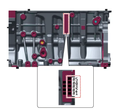
| Class | Mark | Cylinder block crankshaft journal bore inner diameter |
| a | A | 57.000 - 57.006 mm (2.2441 - 2.2443 in.) |
| b | B | 57.006 - 57.012 mm (2.2443 - 2.2446 in.) |
| c | C | 57.012 - 57.018 mm (2.2446 - 2.2448 in.) |
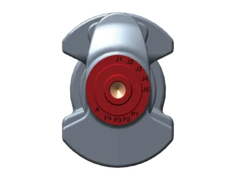
| Class | Mark | Crankshaft main journal outer diameter |
| I | 1 | 51.954 - 51.960 mm (2.0454 - 2.0457 in.) |
| II | 2 | 51.948 - 51.954 mm (2.0452 - 2.0454 in.) |
| III | 3 | 51.942 - 51.948 mm (2.0450 - 2.0452 in.) |
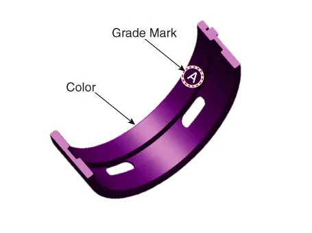
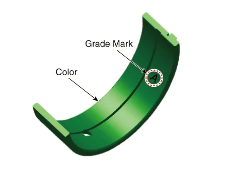
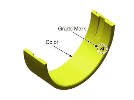
| Class | Color | Bearing thickness |
| A | Sky Blue | 2.518 - 2.521mm (0.0991 - 0.0993in.) |
| B | Black | 2.515 - 2.518mm (0.0990 - 0.0991in.) |
| C | White | 2.512 - 2.515mm (0.0989 - 0.0990in.) |
| D | Light Green | 2.509 - 2.512mm (0.0988 - 0.0989in.) |
| E | Pink | 2.506 - 2.509 mm (0.0987 - 0.0988 in.) |
| F | Yellow | 2.503 - 2.506 mm (0.0985 - 0.0987 in.) |
(7)Select the proper crankshaft main bearing using the below bearing selection table.
| Classification mark for connecting rod | ||||
| a (A) | b (B) | c (C) | ||
| Classification mark for crankshaft pin journal | I (1) | E (Pink) | D (Light green) | C (White) |
| II (2) | D (Light green) | C (White) | B (Black) | |
| III (3) | C (White) | B (Black) | A (Sky Blue) | |
| Classification mark for connecting rod | ||||
| a (A) | b (B) | c (C) | ||
| Classification mark for crankshaft pin journal | I (1) | F (Yellow) | E (Pink) | D (Light green) |
| II (2) | E (Pink) | D (Light green) | C (White) | |
| III (3) | D (Light green) | C (White) | B (Black) | |
2.Measure the crankshaft end play.Check the axial clearance by moving the crankshaft back and forth using a dial gauge.
Crankshaft end play0.100 - 0.280 mm (0.0039 - 1.0110 in.)
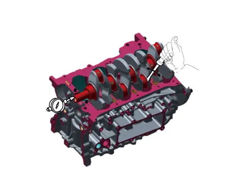
Thrust bearing thickness :2.41 - 2.45 mm (0.09488 - 0.09646 in.)
3.Check the crankshaft main journals and pin journals.Use a micrometer to measure the outer diameter of the crankshaft main journals and pin journals.
Main journal diameter : 51.942 - 51.960 mm (2.0450 - 2.0457 in.)Crank pin diameter :47.954 - 47.972 mm (1.8879 - 1.8887 in.)

ŌĆó Clean the each part before assembling.
ŌĆó Apply new engine oil on the sliding/rotating area before assembling parts.
ŌĆó Always use the new gasket, O-ring and oil seal.
1.Install the crankshaft position sensor wheel (A).
Tightening torque :26.4 - 27.4 N.m (2.7 - 2.8 kgf.m, 19.5 - 20.2 Ib-ft)
2.Install the main bearing.

ŌĆó Install the crankshaft upper bearing which fits to each journal.
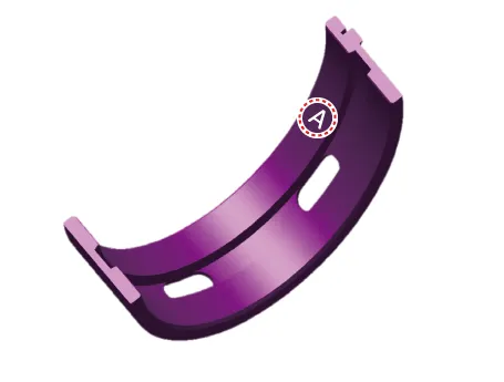
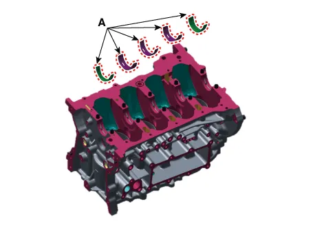
(1)Install the 5 upper bearings (A) by aligning the cylinder block groove and the bearing protrusion.
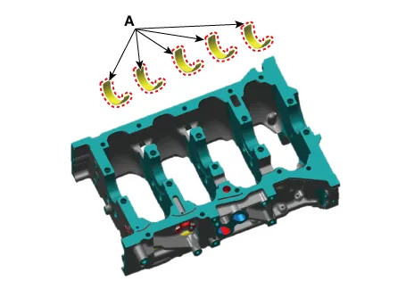
(2)Install the 5 lower bearings (A) by aligning the crank lower case groove and the bearing protrusion.
(3)Apply engine oil after assembling the main bearings.
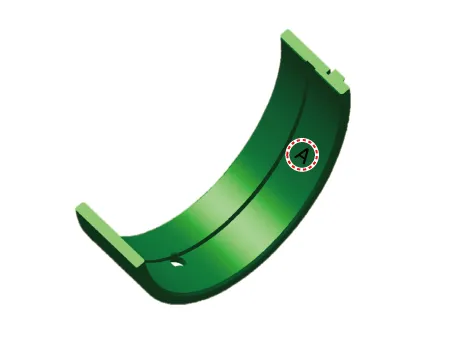
3.Install the thrust bearings.Install the 2 thrust bearings (A) under the cylinder block No. 4 journal, with the oil groove facing outward.

4.Install the crankshaft (A) to the cylinder block.

5.Install the lower crankcase.
(1)Be sure to remove the hardening sealant, foreign substance, oil, dust or moisture remaining on the liquid gasket sealing surface of the lower crankcase.Spray cleaner on the sealing surface and then wipe off with a clean towel.
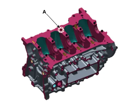
(2)Install the new O-ring (A) to the cylinder block.
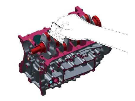
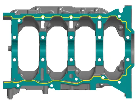
(3)Apply liquid gasket to the lower crankcase mounting surface and then assemble within 5 minutes.
Bead width : ├ś 2.5 - 3.5 mm (0.09843 - 0.13780 in.)Sealant : Loctite 5900H / Threebond 1217H or equivalent
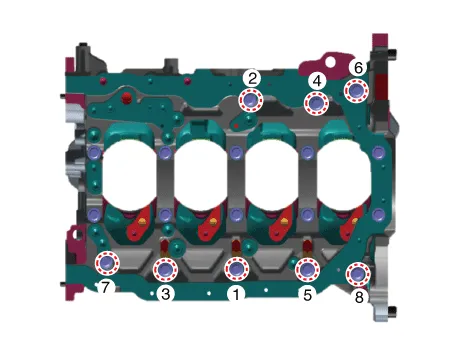
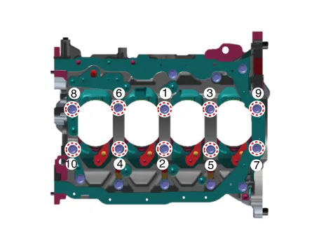
(4)Tighten the crankshaft bearing cap bolts in several passes in the below sequence.
Tightening torque : 27.5 - 31.4 N.m + 120 - 125 ┬░ (2.8 - 3.2 kgf.m + 120 - 125 ┬░, 20.3 - 23.1 lb-ft + 120 - 125 ┬░)


ŌĆó Always use the new bearing cap bolt.
(5)Tighten the lower crankcase mounting bolts in several passes in the below sequence.
Tightening torque : 29.4 - 33.3 N.m (3.0 - 3.4 kgf.m, 21.7 - 24.6 Ib-ft)

(6)Check if the crankshaft rotates smoothly.
6.Check the crankshaft end play.
7.Install the piston and connecting rod assembly. (Refer to the Cylinder Block - "Piston And Connecting Rod")
8.Install the removed parts in reverse order of removal.

ŌĆó When replacing the crankshaft, select and install the appropriate connecting rod bearing according to the pin journal mark on the crankshaft.
ŌĆó Connecting rod bearing selection(Refer to the Cylinder Block - "Piston And Connecting Rod")
 Piston and Connecting Rod
- Removal
ŌĆó Be careful not to damage the parts located under the vehicle
(floor under cover, fuel filter, fuel tank and canister) when raising
the vehicle using the lift.( ...
 Cylinder Block
- Disassembly
ŌĆó Be careful not to damage the parts located under the vehicle
(floor under cover, fuel filter, fuel tank and canister) when raising
the vehicle using the li ...
Other information:
Hyundai Tucson (NX4) 2022-2026 Service Manual: Driver Airbag (DAB) Module and Clock Spring
- Description
ŌĆó Driver Air Bag (DAB)DAB is installed in the steering wheel, and
electrically connected to the SRSCM via clock spring. It is deployed
during frontal impact to protect the driver.
ŌĆó Clock SpringClock spring delivers actuation signal, generated by
the sensors installed ...
Hyundai Tucson (NX4) 2022-2026 Service Manual: Line Pressure Control Solenoid Valve (LINE_VFS)
- Description
ŌĆó Line pressure solenoid valve is a Variable Force Solenoid (VFS) type.
ŌĆó When TCM supplies variable current to solenoid valve, hydraulic pressure is controlled indirectly by solenoid valve.
- Components Location
1. 28 Brake control solenoid valve (28/B_VFS)2. 46 C ...
