Hyundai Tucson: Cylinder Block / Piston and Connecting Rod

• Be careful not to damage the parts located under the vehicle (floor under cover, fuel filter, fuel tank and canister) when raising the vehicle using the lift.(Refer to General Information - "Lift and Support Points")

• Use fender covers to avoid damaging painted surfaces.
• Wait until the engine cools down to room temperature to avoid damaging the cylinder head before removing.
• When handling the metal gasket, be careful not to fold or damage the surface.
• To avoid damage, disconnect the wiring connectors carefully.

• Mark all wirings and hoses to avoid misconnection.
• Turn the crankshaft pulley so that the piston of No.1 cylinder is positioned at the Top Dead Center (TDC).
1.Remove the engine and transaxle assembly from a vehicle.(Refer to the Engine And Transaxle Assembly - "Engine And Transaxle Assembly")
2.Remove the automatic transaxle.(Refer to the Automatic Transaxle System - "Automatic Transaxle")
3.Remove the drive plate.(Refer to Cylinder Block - "Drive Plate")
4.Remove the rear oil seal. (Refer to the Cylinder Block - "Rear Oil Seal")
5.Install the engine to engine stand for disassembly.
6.Remove the cylinder head cover. (Refer to the Cylinder Head Assembly - "Cylinder Head Cover")
7.Remove the oil pan.(Refer to the Lubrication System - "Oil Pan")
8.Remove the timing chain cover.(Refer to the Timing System - “Timing Chain Cover”)
9.Remove the timing chain.(Refer to the Timing System - “Timing Chain”)
10.Remove the Integrated Thermal management Module (ITM).(Refer to the Cooling System - "Integrated Thermal management Module (ITM)")
11.Remove the intake/exhaust/CVVT and camshaft assembly.(Refer to the Cylinder Head Assembly - "CVVT & Camshaft")
12.Remove the intake manifold.(Refer to the Intake And Exhaust System - "Intake Manifold")
13.Remove the exhaust manifold.(Refer to the Intake And Exhaust System - "Exhaust Manifold")
14.Remove the EGR cooler.(Refer to the Intake And Exhaust System - "EGR cooler")
15.Remove the EGR control valve.(Refer to Engine Control / Fuel System - "EGR Control Valve")
16.Remove the cylinder head.(Refer to the Cylinder Head Assembly - "Cylinder Head")
17.Remove the oil pump.(Refer to the Lubrication System - "Oil Pump")
18.Remove the balance shaft assembly.(Refer to the Lubrication System - "Balance Shaft Assembly")
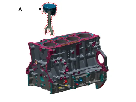
19.Remove the piston and connecting rod assembly.
(1)Remove the carbon deposits on the top of cylinder.
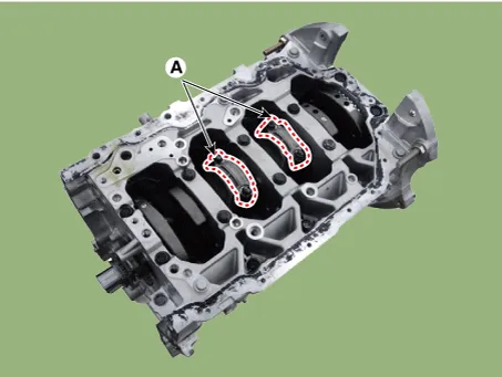
(2)Remove the connecting rod bearing cap (A).


• Mark the cylinder No. on the connecting rod and cap for correct installation when reinstalling.
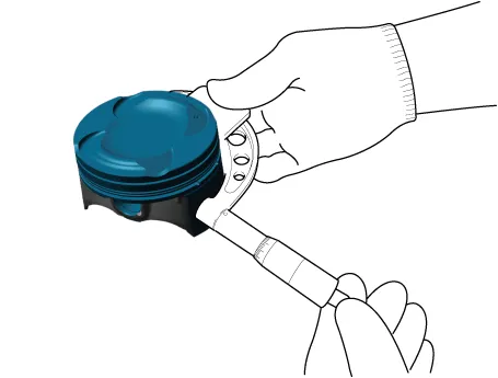
(3)Push the piston and connecting rod assembly (A) together with the upper bearing through the top of the cylinder block.

• Keep the connecting rod and cap with the bearing assembled
• Arrange the piston and connecting rod assemblies in the correct order.
• Mark the cylinder No. so that the piston and connecting rod assembly removed from each cylinder can be installed to original positon.
20.Measure the clearance between the piston and piston pin. Try to move the piston back and forth on the piston pin.If any movement is felt, replace the piston and piston pin as a set.
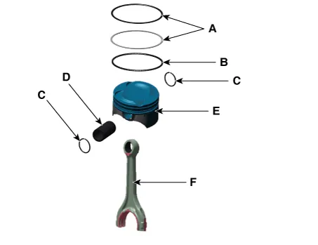
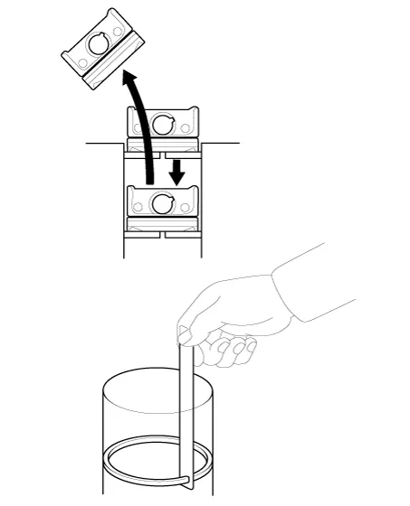
21.Remove piston rings.
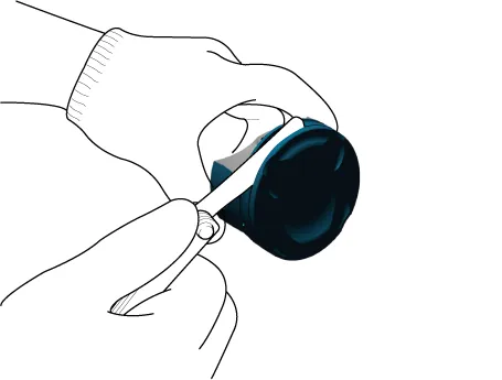
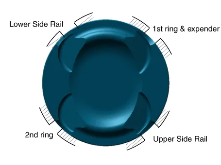
(1)Remove the 2 piston rings (A) using a piston ring expander.
(2)Remove the oil ring (B) with hand.

• When removing the oil ring, be careful not to excessively widen the both ends of oil ring. Otherwise, oil ring can be broken.

• Arrange the piston rings in the correct order.
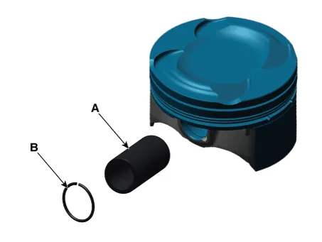
22.Separate the piston and connecting rod.
(1)Remove the snap ring (C).
(2)Remove the piston pin (D) from the piston.
(3)Separate the piston (E) and connecting rod (F).
1.Inspect the side clearance of connecting rod.Measure the side clearance of connecting rod big end using a feeler gauge.
Specified value: 0.1 - 0.25 mm (0.00394 - 0.00984 in.) Limit value: 0.35 mm (0.01378 in.)
• If the side clearance is out of the limit value, replace the connecting rod.
• If the side clearance is still out of the limit value even after replacing the connecting rod, replace the crankshaft.
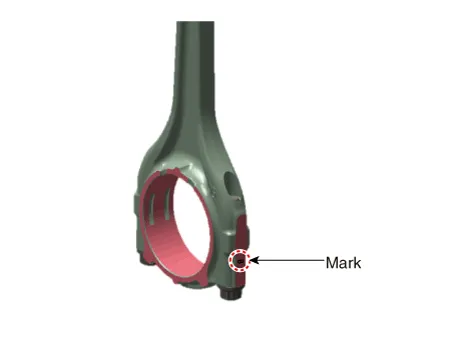
2.Inspect the oil clearance of connecting rod bearing.
(1)Check the alignment marks of connecting rod and connecting rod cap for correct installation.
(2)Loosen the 2 connecting rod cap bolts.
(3)Remove the connecting rod cap and lower bearing.
(4)Clean the crankshaft pin journals and bearings.
(5)Place the plastic gauge in axial direction.
(6)Reinstall the lower bearing and connecting rod cap and then tighten the bolts to the specified torque (Do not reuse the bolts).
Tightening torque17.7 - 21.6 N.m (1.8 - 2.2 kgf.m, 13.0 - 15.9 lb-ft) + 88 - 92°

• Do not turn the crankshaft.
(7)Remove the connecting rod cap again.
(8)Measure the widest part of the plastic gauge.
Standard oil clearance :0.032 - 0.050 mm (0.00126 - 0.00197 in.)
(9)If the measured value of plastic gauge is out of the specified value, replace the bearing with a new one having the same classification color and then remeasure the oil clearance

• Do not adjust the clearance by machining the bearing or cap.
(10)If the remeasured value is still out of the specified value, install the next larger or smaller bearing and then remeasure the oil clearance.

• If the proper oil clearance is not obtained even after assembling the next larger or smaller bearing, replace the crankshaft and then inspect again from step 1.
• If the classification marks are indecipherable because of the accumulation of dirt and dust, do not scrub them with a wire brush or scraper. Clean them only with solvent or detergent.
| Class | Mark | Inside Diameter |
| a | A | 51.000 - 51.006 mm (2.00787 - 2.00811 in.) |
| b | B | 51.006 - 51.012 mm (2.00811 - 2.00834 in.) |
| c | C | 51.012 - 51.018 mm (2.00834 - 2.00858 in.) |
| Class | Mark | Crankshaft pin journal outer diameter |
| I | 1 | 47.966 - 47.972 mm (1.8884 - 1.8887 in.) |
| II | 2 | 47.960 - 47.966 mm (1.8882 - 1.8884 in.) |
| III | 3 | 47.954 - 47.960 mm (1.8879 - 1.8882 in.) |
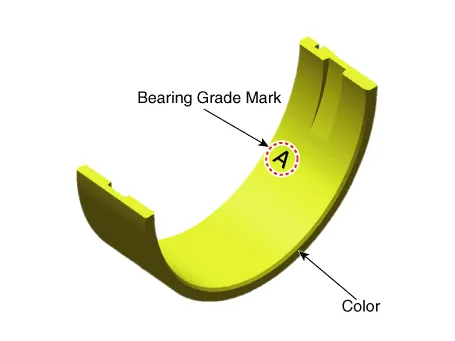
| Class | Color | Connecting rod bearing thickness |
| A | Sky Blue | 1.507 - 1.510 mm (0.0593 - 0.0594 in.) |
| B | BLACK | 1.504 - 1.507 mm (0.0592 - 0.0593 in.) |
| C | WHITE | 1.501 - 1.504 mm (0.0591 - 0.0592 in.) |
| D | LIGHT GREEN | 1.498 - 1.501 mm (0.0590 - 0.0591 in.) |
| E | PINK | 1.495 - 1.498 mm (0.0589 - 0.0590 in.) |
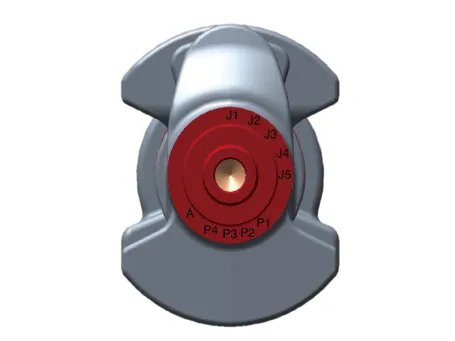
(11)Select the proper connecting rod bearing using the below bearing selection table.
| Classification mark for connecting rod | ||||
| A | B | C | ||
| Classification mark for crankshaft pin journal | 1 | E (Pink) | D (Light green) | C (White) |
| 2 | D (Light green) | C (White) | B (Black) | |
| 3 | C (White) | B (Black) | A (Sky Blue) | |
3.Inspect the connecting rod.
(1)When installing the new connecting rod, make sure that the notches for holding the bearing in place are on the same side.
(2)Replace the connecting rod if it is damaged on the thrust faces at either end. Also if step wear or a severely rough surface of the inside diameter of the small end is apparent, the connecting rod must be replaced as well.
(3)Using a connecting rod aligning tool, measure the bend/twist of connecting rod and if the measured value is close to the allowable value, modify the connecting rod using the press machine. If the bend/twist is excessive, replace the connecting rod.
Allowable bend of connecting rod :0.05mm (0.0020 in.) or less for 100mm (3.94 in.)Allowable twist of connecting rod :0.10mm (0.0039 in.) or less for 100mm (3.94 in.)

• In the absence of bearings, there should be no side step difference.
1.Clean the piston
(1)Remove the carbon deposits on the top of the piston using a scraper.
(2)Clean the piston ring groove using a broken ring.
(3)Thoroughly clean the piston using solvent and brush.

• Do not use the wire brush.
2.Check the clearance by calculating the difference between the cylinder bore inner diameter and the piston outer diameter.
Clearance between piston and cylinder: 0.04 - 0.06 mm (0.0016 - 0.0024 in.)
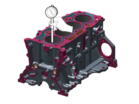
(1)Measure the cylinder bore inner diameter at position in the thrust and axial direction using a cylinder bore gauge.
Cylinder bore diameter : 88.50 - 88.53 mm (3.4842 - 3.4854 in.)
(2)Measure the piston outer diameter at 13.0 mm (0.51181 in.) from bottom land of the piston.
Piston outside diameter : 88.45 - 88.48 mm (3.4823 - 3.4835 in.)
3.Select the piston matching with the cylinder bore class. (Same classification mark)
Piston-to-cylinder clearance :0.04 - 0.06 mm (0.0016 - 0.0024 in.)
(1)Check the cylinder bore size mark on the lateral side of cylinder block.
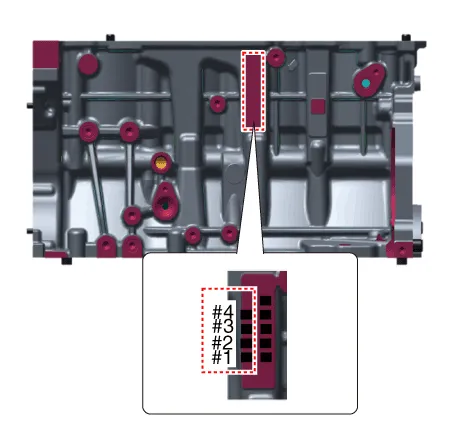
| Class | Mark | Cylinder bore inner diameter |
| a | A | 88.50 - 88.51 mm (3.4842 - 3.4846 in.) |
| b | B | 88.51 - 88.52 mm (3.4846 - 3.4850 in.) |
| c | C | 88.52 - 88.53 mm (3.4850 - 3.4854 in.) |
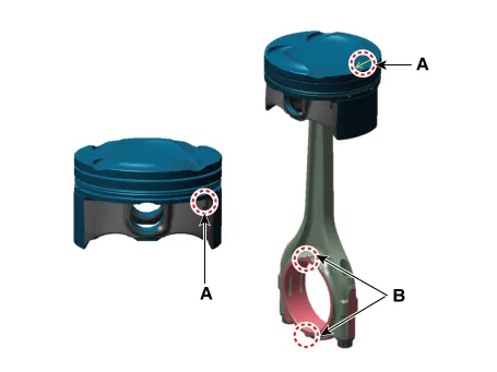
(2)Check the piston outer diameter size mark (A) on the top of piston.
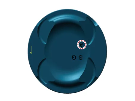
| Mark | Piston outer diameter |
| A | 88.45 - 88.46 mm (3.4823 - 3.4827 in.) |
| B | 88.46 - 88.47 mm (3.4827 - 3.4831 in.) |
| C | 88.47 - 88.48 mm (3.4831 - 3.4835 in.) |
1.Inspect the side clearance of piston ring.Measure the clearance between the piston ring groove and the piston ring using a feeler gauge.
Piston ring groove width dimension of pistonNo.1 ring : 1.235 - 1.250 mm (0.04862 - 0.04921 in.)No.2 ring : 1.230 - 1.250 mm (0.04843 - 0.04921 in.) Oil ring: 2.010 - 2.025 mm (0.07913 - 0.07972 in.)Piston ring width dimension No. 1 ring: 1.170 - 1.190 mm (0.04606 - 0.04685 in.) No. 2 ring: 1.170 - 1.190 mm (0.04606 - 0.04685 in.) Oil ring: 1.910 - 1.970 mm (0.07520 - 0.07756 in.) Side clearance between piston and piston ring No.1 ring: 0.045 - 0.080 mm (0.00177 - 0.00315 in. No.2 ring: 0.040 - 0.080 mm (0.00157 - 0.00315 in. Oil ring: 0.040 - 0.115 mm (0.0015 - 0.0045 in.)
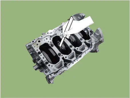
2.Inspect the piston ring end gap.Insert the piston ring into the cylinder to measure the piston ring end gap. At this time, gently pressing the ring with a piston so that the piston ring is positioned at the correct angle to the cylinder wall. Measure the end gap using a feeler gauge and replace the piston ring if end gap exceeds limit value.
Piston ring end gapSpecified valueNo. 1 ring: 0.14 - 0.19 mm (0.00669 - 0.00748 in.)No. 2 ring: 0.30 - 0.40 mm (0.01181 - 0.01575 in.)Oil ring: 0.10 - 0.40 mm (0.00394 - 0.01575 in.)
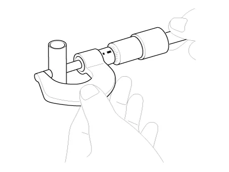
1.Measure the outer diameter of piston pin.
Piston pin diameter :19.997 - 20.000mm (0.7873 - 0.7874 in.)
2.Measure the clearance between the piston pin and the piston.
Piston pin-to-piston clearance :0.003 - 0.010 mm (0.00012 - 0.00039 in.)
3.Measure the clearance between the outer diameter of piston pin and the inner diameter of connecting rod small end.
Piston pin-to-connecting rod interference :0.005 - 0.014 mm (0.00020 - 0.00055 in.)

• Clean the each part before assembling.
• Apply new engine oil on the sliding/rotating surface before assembling parts.
• Always use the new gasket, O-ring and oil seal.
1.Assemble the piston and the connecting rod.
(1)Insert the snap ring (A) into the one side of piston pin holes.

(2)Align the piston front mark (A) and the connecting rod front mark (B).

(3)Insert the piston pin (A) into the piston pin hole and the small end bore of connecting rod.
(4)Insert the snap ring (B) into the another piston pin hole.

• Before assembling the piston pin, apply a sufficient amount of engine to the outer surface of piston, inner surface of piston hole and connecting small end bore
• When inserting, be careful not to damage or scratch the connecting rod small end hole, piston pin and piston pin hole.
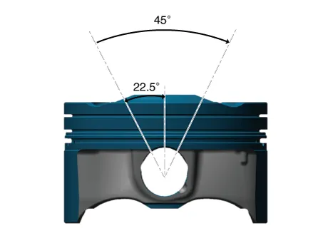
• Set the snap ring so that it contacts securely with the whole groove of the piston pin hole.
• Set the snap ring so that its cutting section is positioned at the 45 ˚ range of upper direction.
2.Install the piston ring.
(1)Install the oil ring expander and 2 side rails with hand.
(2)Using a piston ring expander, install the 2 compression rings with the code mark facing upward.
(3)Install the piston rings to ensure the ring ends are positioned as shown below.
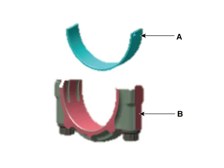
3.Install the connecting rod bearing.
(1)Align the connecting rod/bearing cap (A) grooves and the protrusion of bearing (B).
(2)Install the bearing (B) to the connecting rod and bearing cap (A).
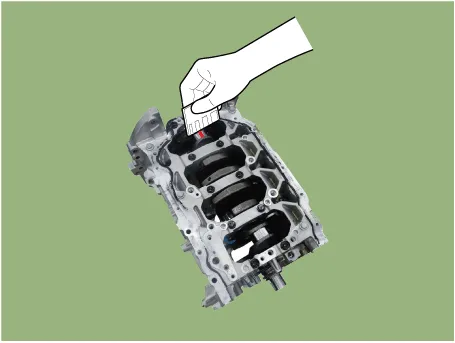
4.Install the piston and connecting rod assembly.

• Before assembling the piston, apply a small amount of engine oil on the piston ring groove and the inner surface of cylinder.
• The piston front mark (A) and the connecting rod front mark (B) should face the timing chain.
(1)Install the piston ring compressor while checking that the piston ring is securely in place. Put the piston in the cylinder and then tap it in using the wooden handle of a hammer.
(2)Stop once the piston ring is inserted into the cylinder and then recheck the alignment of journal and connecting rod before pushing the piston into place.
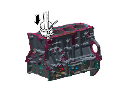

• Insert the piston while pressing down the piston ring compressor to prevent the piston ring expansion before piston ring is inserted into the cylinder.
(3)Install the connecting rod caps (A) and then tighten the bolts to the specified torque.
Tightening torque : 17.7 - 21.6 N.m + 88 - 92° (1.8 - 2.2 kgf.m + 88 - 92°, 13.0 - 15.9 lb-ft + 88 - 92°)

• Always use the new connecting rod bearing cap bolt.
5.Install in the reverse order of removal.
 Rear Oil Seal
- Replacement
• Be careful not to damage the parts located under the vehicle
(floor under cover, fuel filter, fuel tank and canister) when raising
the vehicle using the li ...
 Crankshaft
- Disassembly
• Be careful not to damage the parts located under the vehicle
(floor under cover, fuel filter, fuel tank and canister) when raising
the vehicle using the li ...
Other information:
Hyundai Tucson (NX4) 2022-2025 Owner's Manual: Explanation of Scheduled Maintenance Items
Engine Oil and Filter
The engine oil and filter should be
changed at the intervals specified
in the maintenance schedule. If the
vehicle is driven in severe conditions,
more frequent oil and filter changes are
required.
Drive Belts
Inspect all drive belts for evidence
of cuts, cracks, ...
Hyundai Tucson (NX4) 2022-2025 Service Manual: Front Hub / Knuckle / Tone Wheel
- Components
1. Front brake disc2. Front hub assembly3. Dust cover4. Front knuckle
- Removal
• When lifting a vehicle using a lift, be careful not to damage
the lower parts of the vehicle (floor under cover, fuel filter, fuel
tank, canister).(Refer to General I ...
