Hyundai Tucson: Cylinder Block / Cylinder Block

• Be careful not to damage the parts located under the vehicle (floor under cover, fuel filter, fuel tank and canister) when raising the vehicle using the lift.(Refer to General Information - "Lift and Support Points")

• Use fender covers to avoid damaging painted surfaces.
• Wait until the engine cools down to room temperature to avoid damaging the cylinder head before removing.
• When handling the metal gasket, be careful not to fold or damage the surface.
• To avoid damage, disconnect the wiring connectors carefully.

• Mark all wirings and hoses to avoid misconnection.
• Turn the crankshaft pulley so that the piston of No.1 cylinder is positioned at the Top Dead Center (TDC).
1.Remove the engine and transaxle assembly from a vehicle.(Refer to the Engine And Transaxle Assembly - "Engine And Transaxle Assembly")
2.Remove the automatic transaxle.(Refer to the Engine And Transaxle Assembly - "Engine And Transaxle Assembly")
3.Remove the drive plate.(Refer to Cylinder Block - "Drive Plate")
4.Remove the rear oil seal. (Refer to the Cylinder Block - "Rear Oil Seal")
5.Install the engine to engine stand for disassembly.
6.Remove the cylinder head cover. (Refer to the Cylinder Head Assembly - "Cylinder Head Cover")
7.Remove the oil pan.(Refer to the Lubrication System - "Oil Pan")
8.Remove the timing chain cover.(Refer to the Timing System - “Timing Chain Cover”)
9.Remove the timing chain.(Refer to the Timing System - “Timing Chain”)
10.Remove the Integrated Thermal management Module (ITM).(Refer to the Cooling System - "Integrated Thermal management Module (ITM)")
11.Remove the intake/exhaust/CVVT and camshaft assembly.(Refer to the Cylinder Head Assembly - "CVVT & Camshaft")
12.Remove the intake manifold.(Refer to the Intake And Exhaust System - "Intake Manifold")
13.Remove the exhaust manifold.(Refer to the Intake And Exhaust System - "Exhaust Manifold")
14.Remove the EGR cooler.(Refer to the Intake And Exhaust System - "EGR cooler")
15.Remove the EGR control valve.(Refer to Engine Control / Fuel System - "EGR Control Valve")
16.Remove the cylinder head.(Refer to the Cylinder Head Assembly - "Cylinder Head")
17.Remove the oil pump.(Refer to the Lubrication System - "Oil Pump")
18.Remove the balance shaft assembly.(Refer to the Lubrication System - "Balance Shaft Assembly")
19.Remove the water pump.(Refer to the Cooling System - "Water Pump")
20.Remove the alternator.(Refer to the Engine Electrical System - "Alternator")
21.Refer to the oil filter & oil cooler.(Refer to the Lubrication System - "Oil Filter & Oil Cooler")
22.Remove the lower crankcase.(Refer to the Cylinder Block - "Crankshaft")
23.Remove the piston and connecting rod assembly.(Refer to the Cylinder Block - "Piston And Connecting Rod")
24.Remove the crankshaft.(Refer to the Cylinder Block - "Crankshaft")
25.Remove the water jacket insert.(Refer to the Cylinder Block - "Water Jacket Insert")
26.Remove the knock sensor.(Refer to the Engine Control/Fuel System - "Knock Sensor (KS)")
27.Remove the Crankshaft Position Sensor (CKPS).(Refer to the Engine Control/Fuel System - "Crankshaft Position Sensor (CKPS)")
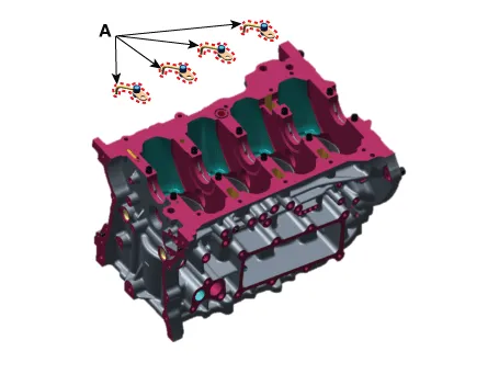
28.Remove the piston cooling oil jet (A).

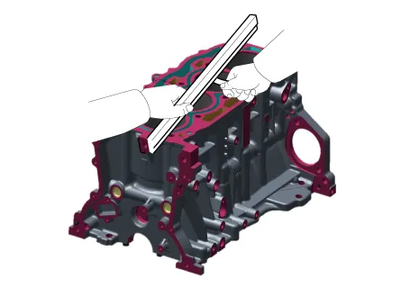
1.Remove the gasket debris on the top of cylinder block using a scraper.
2.Clean the cylinder block thoroughly with a soft brush and solvent.
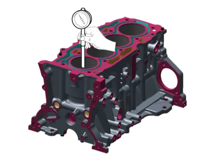
3.Measure the flatness of the top surface of cylinder block.Measure the flatness of the surface in contact with the cylinder head gasket using the precise square ruler and feeler gauge.
Flatness of cylinder block gasket surface :Specified value: 0.05 mm (0.00197 in.) or less (0.02 mm (0.00197 in.) or less-100 mm (3.93701 in.) × 100 mm (3.93701 in.))
4.Visually inspect the inside of cylinder bore for scratches, etc., and replace the cylinder block if noticeable scratches are found.
5.Measure the cylinder bore inner diameter in the axial and axial orthogonal directions using a cylinder bore gauge.
Cylinder bore diameter :88.50 - 88.53 mm (3.48425 - 3.48543 in.)

• Clean the each part before assembling.
• Apply new engine oil on the sliding/rotating surface before assembling parts.
• Always use the new gasket, O-ring and oil seal.
1.Install the piston cooling oil jet (A).
Tightening torque :8.8 - 10.8 N.m (0.9 - 1.1 kgf.m, 6.5 - 8.0 lb-ft)
2.Install the crankshaft.(Refer to the Cylinder Block - "Crankshaft")
3.Inspect the crankshaft end play.(Refer to the Cylinder Block - "Crankshaft")
4.Remove the lower crankcase and then inspect the oil clearance of crankshaft bearing. (Refer to the Cylinder Block - "Crankshaft")
5.Install the piston and connecting rod assembly.(Refer to the Cylinder Block - "Piston And Connecting Rod")
6.Inspect the oil clearance of connecting rod bearing cap.(Refer to the Cylinder Block - "Piston And Connecting Rod")
7.Inspect the connecting rod end play.(Refer to the Cylinder Block - "Piston And Connecting Rod")
8.Install in the reverse order of removal.

• Crankshaft main bearing selection(Refer to the Cylinder Block - "Crankshaft")
• Piston selection(Refer to the Cylinder Block - "Piston And Connecting Rod")
 Crankshaft
- Disassembly
• Be careful not to damage the parts located under the vehicle
(floor under cover, fuel filter, fuel tank and canister) when raising
the vehicle using the li ...
 Cooling System
...
Other information:
Hyundai Tucson (NX4) 2022-2025 Service Manual: High Pressure Fuel Pump
- Specification
ItemSpecification
Coil Resistance (Ω)0.53 - 0.57 [20°C (68°F)]
- Circuit Diagram
Harness Connector
- Removal
1.Release residual pressure in fuel line.(Refer to Fuel Delivery System - "Release Residual Pressure in Fuel Line")
2.Turn the ignition switch OFF ...
Hyundai Tucson (NX4) 2022-2025 Service Manual: Rear Shock Absorber
- Components
1. Lock nut2. Insulator assembly 3. Dust cover 4. Rear shock absorber
- Removal
• When lifting a vehicle using a lift, be careful not to damage
the lower parts of the vehicle (floor under cover, fuel filter, fuel
tank, canister).(Refer to General I ...
