Hyundai Tucson: Timing System / Timing Chain Cover

• Be careful not to damage the parts located under the vehicle (floor under cover, fuel filter, fuel tank and canister) when raising the vehicle using the lift.(Refer to General Information - "Lift and Support Points")

• In case of removing the high pressure fuel pump, high pressure fuel pipe, delivery pipe, andinjector, there may be injury caused by leakage of the high pressure fuel. So don’t do any repairwork right after engine stops.

• Use fender covers to avoid damaging painted surfaces.
• To avoid damage, unplug the wiring connectors carefully while holding the connector portion.
• Remove the variable force solenoid valve (VFS) and E-CVVT cover first when removing thetiming chain cover.

• Mark all wiring and hoses to avoid misconnection.
1.Disconnect the battery negative terminal.
2.Remove the engine cover.(Refer to Engine and Transaxle Assembly - "Engine Cover")
3.Remove the engine room under cover.(Refer to Engine and Transaxle Assembly - "Engine Room Under Cover")
4.Drain the engine oil.(Refer to Lubrication System - "Engine Oil")
5.Remove the drive belt and water pump belt.(Refer to Drive Belt System - "Drive Belt")
6.Remove the crankshaft damper pulley.(Refer to Drive Belt System - "Crankshaft Damper Pullty")
7.Remove the drive belt tensioner.(Refer to Drive Belt System - "Drive Belt Tensioner")
8.Remove the cylinder head cover.(Refer to Cylinder Head Assembly - "Cylinder Head Cover")
9.Remove the oil level gauge.(Refer to Lubrication system - "Oil level gauge & pipe")
10.Remove the A/C compressor mounting bolts.(Refer to Heating, Ventilation and Air Conditioning System - "Compressor")
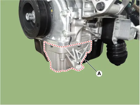
11.Remove the A/C compressor mounting bracket (A).
Tightening torque :19.6 - 23.5 N.m (2.0 - 2.4 kgf.m, 14.4 - 17.3 Ib.ft)
12.Remove the oil pan.(Refer to Lubrication System - "Oil Pan")
13.Install the jack to the edge of ladder frame.

• Put the rubber block between the jack and ladder frame to avoid damaging the ladder frame.
• Be careful not to damage the balance shaft and oil pump.
14.Remove the engine mounting support bracket and the engine mounting bracket.(Refer to Engine and Transaxle Assembly System - "Engine Mounting")
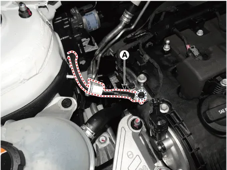
15.Disconnect the engine ground cable (A) from the the timing chain cover.
Tightening torque :6.8 - 9.8 N.m (0.7 - 1.0 kgf.m, 5.1 - 7.2 lb-ft)
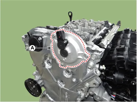
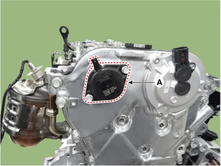
16.Remove the engine support bracket (A).

17.Remove the E-CVVT cover (A).

• Be careful not to apply external force to the brush after removing the cover.
18.Remove the variable force solenoid valve (A).


• When removing the timing chain cover, be sure to remove the variable force solenoidvalve(VFS) first.
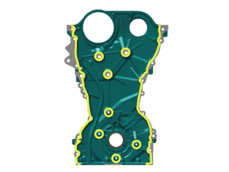
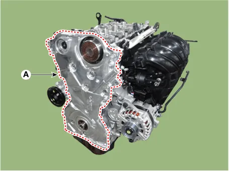
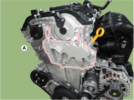
19.Remove the timing chain cover (A).


• When removing the timing chain cover, be careful not to damage the contact surfaces ofcylinder block, cylinder head and lower crankcase.
1.Check if the oil flows inside the E-CVVT cover.If the oil flows inside the E-CVVT cover, replace the E-CVVT cover
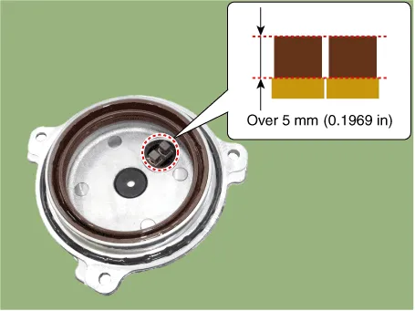
2.Check the connector brush wear condition.If the brush is worn down, replace the E-CVVT cover.
1.Install the timing chain cover.
(1)Make sure to remove the hardening sealant, foreign materials, oil, dust and moisturegathered in the liquid gasket sealing surface (cam carrier, cylinder head, cylinder block, lowercrankcase). Then, spray the cleaner on the sealing surface and wipe off with a cleantowel.
(2)Apply a sealant for liquid gasket to the interface between the cam carrier, cylinder head,cylinder block and lower crankcase.
Bead width : Ø 3.0 - 5.0 mm (0.11 - 0.19 in.)Sealant : MS 721-40 AA or AA0

(3)The part must be assembled within 5 minutes after sealant was applied on the mountingsurface of liquid gasket of timing chain cover.
Bead width : Ø 3.0 - 5.0 mm (0.11 - 0.19 in.)Sealant : MS 721-40 AA or AA0
(4)The dowel pins on the cylinder block and holes on the timing chain cover should be used asa reference in order to assemble the timing chain cover (A) to be in exact position.
Tightening torque :Bolt (B) : 9.8 - 11.7 N.m (1.0 - 1.2 kgf.m, 7.2 - 8.6 Ib.ft)Bolt (C) : 18.6 - 22.5 N.m (1.9 - 2.3 kgf.m, 13.7 - 16.6 Ib.ft)Bolt (D) : 9.8 - 11.7 N.m (1.0 - 1.2 kgf.m, 7.2 - 8.6 Ib.ft)
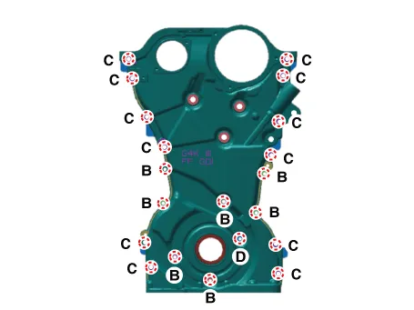

• The engine starting or pressure tests should not be performed within 30 minutes after thetiming chain cover was assembled.
• Always install the timing chain cover mounting bolt (D) with a new one.
2.Replace the front oil seal if neccesary.(Refer to Timing System - "Front oil Seal")
3.Remove it by breaking the center of E-CVVT motor plug (A).
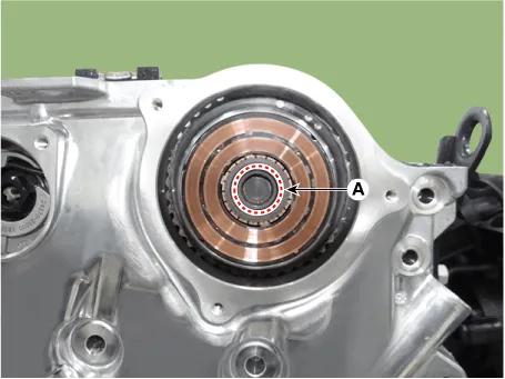

• Remove after 30 minutes of switching "OFF" the ignition to drain out the oil inside the E-CVVTmotor plug.
• Do not tilt the front of engine (timing chain cover side) downward as residual oil may flow outduring E-CVVT motor plug removal.
• If oil flows out during E-CVVT motor plug removal, wipe off immediately and block the motorshaft inlet with a clean towel.
4.Clean the E-CVVT motor plug mounting surface (A) with oil cleaner.

• If the surface is not cleaned, E-CVVT motor plug may be separated due to diminishedseparation force from residual oil.
• When spraying oil cleaner, block around the motor shaft inlet and rotor gap with a clean towelto prevent inflow of oil from flowing into the rotor gap.
5.When reusing the E-CVVT cover, inspect the below items.
(1)If there is sign of leakage from inside the E-CVVT cover, replace it with a new one.
(2)Check the connector brush wear condition.
Specification : Over 5 mm (0.1969 in.)
(3)Check for damaged oil seal and replace any damaged E-CVVT cover with a new one.
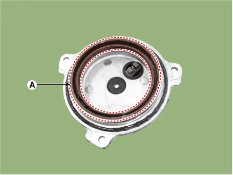
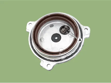
(4)After inspecting E-CVVT, if no problem is found, replace the o-ring (A) with a new one.
6.Install the E-CVVT cover.
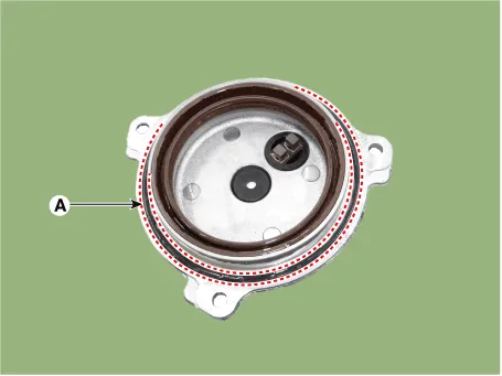
(1)Apply engine oil to the oil seal lip (A).

• When applying oil, keep the connector brush (A) clean from foreign materials.
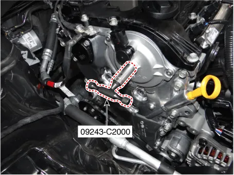
(2)Insert the SST(09243-C2000) into the E-CVVT motor shaft.
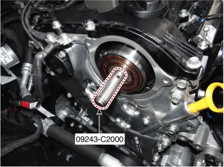

• Correctly mount SST onto the motor shaft.
(3)Slowly push the E-CVVT cover (A) until it is flushed with the timing chain cover surface.
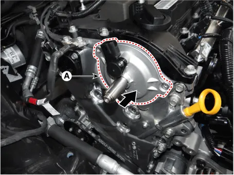

• Installing the E-CVVT cover without SST may cause oil leakage inside the E-CVVT motor due todamaged or separated E-CVVT oil seal.
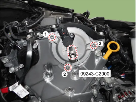
(4)Pre-tighten the bolts in the below sequence, and then remove the SST (09243-C2000).
Tightening torque :0.9 - 1.9 N.m (0.1 - 0.2 kgf.m, 0.7 - 1.4 Ib.ft)
(5)Tighten the bolts to the specified torque in the sequence below.
Tightening torque : 9.8 - 11.7 N.m (1.0 - 1.2 kgf.m, 7.2 - 8.6 Ib.ft)
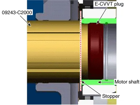
7.Install the E-CVVT plug.
(1)Insert the plug into the E-CVVT cover hole using SST (09243-C2000).
(2)Mount the stopper of SST so that it sits at the end of E-CVVT motor shaft.
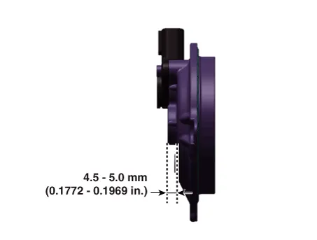
8.Inspect the pressed depth of E-CVVT plug.
(1)By using a steel ruler, measure the distance from E-CVVT cover center boss to the end ofmotor shaft (①).
(2)By using a steel ruler, measure the distance from E-CVVT cover center boss to the end of E-CVVT plug (②).
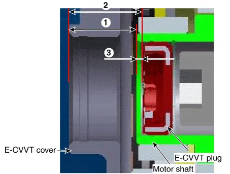
(3)Calculate the pressed depth (③) of motor plug.If out of specification, reinstall after replacing the E-CVVT plug with a new one.
Pressed depth : ③ = ② - ①Specification : 1.1 - 2.1 mm (0.0433 - 0.0826 in.)
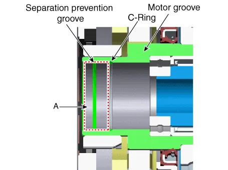
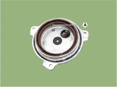
9.Insert the E-CVVT cover plug so that the protrusion reach to E-CVVT cover groove correctly.
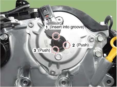

• Check how much protrude after installing the E-CVVT plug.
• Be careful that the plug is not inserted inside E-CVVT cover beyond the regulated range.
10.Install the variable force solenoid valve(VFS)(A).
Tightening torque : 9.8 - 11.7 N.m (1.0 - 1.2 kgf.m, 7.2 - 8.6 Ib.ft)

• Do not reuse the variable force solenoid valve (VFS) if it is dropped.
• When installing the Variable Force Solenoid Valve (VFS), pay attention to the following points.
1)After replacing the variable force solenoid valve (VSF) O-ring (A) with a new one, apply engine oil to the new O-ring (A).
2)Push the variable force solenoid valve (VFS) to the end of the timing chain cover mountingsurface, and then pre-tighten the bolts.
3)Tighten the variable force solenoid valve (VFS) with specified torque.
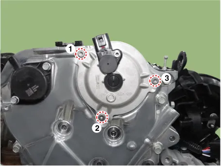
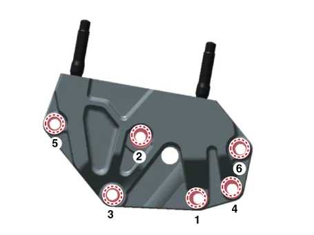
11.Install the engine support bracket (A).
Tightening torque : 96.1 - 114.7 N.m (4.0 - 4.5 kgf.m, 70.8 - 84.6 Ib.ft)
(1)Pre-tighten the bolts in the order of 1→2→3
(2)Turn the bracket counterclockwise and install the bolt 1.
(3)Install in order of 2 → 3 → 4 → 5 →6 .
12.Installation is in the reverse order of removal.
 Front Oil Seal
- Replacement
• Be careful not to damage the parts located under the vehicle
(floor under cover, fuel filter, fuel tank and canister) when raising
the vehicle using the li ...
 Timing Chain
- Removal
• Be careful not to damage the parts located under the vehicle
(floor under cover, fuel filter, fuel tank and canister) when raising
the vehicle using the lift.( ...
Other information:
Hyundai Tucson (NX4) 2022-2025 Service Manual: Components and Components Location
- Component Location
1. Head lamp (Low & High)2. Head lamp (Low)3. Head lamp (High)4. Turn signal lamp5. Daytime running light (DRL) & Positioning lamp6. Side repeater lamp7. Overhead console lamp8. Vanity lamp9. Rear personal lamp10. Luggage lamp11. Head lamp (Static Bending Light)12. ...
Hyundai Tucson (NX4) 2022-2025 Service Manual: Ignition Coil
- Description
The ignition coil is mounted on the top side of the cylinder head cover
end. The ignition coil consists of the primary coil that receives
battery power and the secondary coil that generates high voltage.When
the current in the primary coil is cut off by the ignition signal of ...
