Hyundai Tucson: ESC (Electronic Stability Control) System / Description and Operation
- Description of ESP
Electronic Stability Control (ESC) recognizes critical driving
conditions, such as panic reactions in dangerous situations, and
stabilizes the vehicle by individual wheel braking and engine control
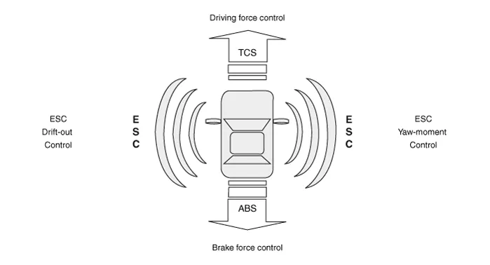
input.ESC adds an additional function known as Active Yaw Control (AYC)
to the ABS, TCS, EBD and ESC functions. On contrary, the ABS/TCS
function controls wheel slip during braking and accelerating, and thus,
mainly intervenes in the longitudinal dynamics of the vehicle, and the
active yaw control stabilizes the vehicle on the vertical axis.This is
achieved by individual wheel brake intervention and adaptation of
momentary engine torque with no need for any action to be taken by the
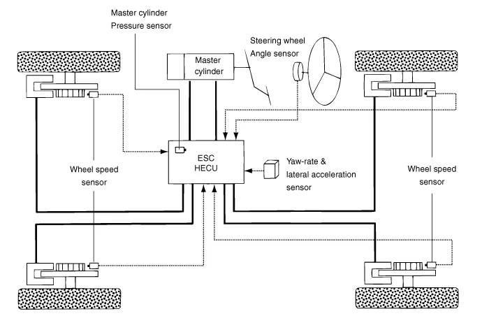
driver.ESC essentially consists of three assemblies : the sensors, the
electronic control unit and the actuators.The stability control feature
works under all driving and operating conditions. Under certain driving
conditions, the ABS/TCS function can be activated simultaneously with
the ESC function in response to a command by the driver.In the event of a
failure of the stability control function, the basic safety function,
ABS, is still maintained.
Description of ESP Control
ESC system consists of ABS/EBD, TCS and AYC functions.ABS/ EBD function :
The ECU changes the active sensor signal (current shift) coming from
the four wheel sensors into square waves. By using the input of above
signals, the ECU calculates the vehicle speed and the acceleration &
deceleration of the four wheels. And, the ECU determines whether the
ABS/EBD should be actuated or not.TCS function prevents the wheel slip
of drive direction by adding the brake pressure and engine torque
reduction via CAN communication. TCS function uses the wheel speed
sensor signal to determine the wheel slip as far as ABS function.AYC
function prevents unstable maneuver of the vehicle. To determine the
vehicle maneuver, AYC function uses the maneuver sensor signals (Yaw
Rate Sensor, Lateral Acceleration Sensor, and Steering Wheel Angle
Sensor).If vehicle maneuver is unstable (Over Steer or Under Steer), AYC
function applies the brake pressure on certain wheel, and sends engine
torque reduction signal by CAN.After the ignition on, the ECU
continuously diagnoses the system for failures (self-diagnosis). If a
system failure is detected, the ECU informs driver of the system failure
through the BRAKE/ABS/ESC warning lamp (fail-safe warning).
Input and Output Diagram
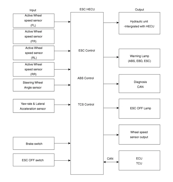
- ESC Operation Mode
1.STEP 1The ESC analyzes the intention of the driver.

2.STEP 2It analyzes the movement of the ESC vehicle.

3.STEP 3The HECU calculates the required strategy, then actuates the
appropriate valves and sents torque control requests via CAN to
maintain vehicle stability.

ESC Hydraulic System Diagram
1.ESC Non-operation : Normal braking.
| Solenoid Valve | Continuity | Valve | Motor Pump | TC Valve |
| IN (NO) | OFF | OPEN | OFF | OFF |
| OUT (NC) | OFF | CLOSE |
2.ESC operation
| Solenoid Valve | Continuity | Valve | Motor Pump | TC Valve |
Understeering
(Only inside of rear wheel) | IN (NO) | OFF | OPEN | ON | ON |
| OUT (NC) | OFF | CLOSE |
Oversteering
(Only outside of front wheel) | IN (NO) | OFF | OPEN |
| OUT (NC) | OFF | CLOSE |
Warning Lamp Control
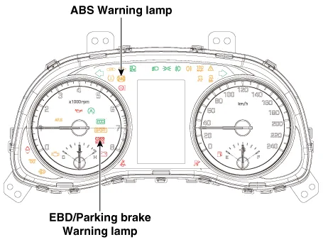
ABS Warning Lamp module
The active ABS warning lamp module indicates the self-test and failure status of the ABS. The ABS warning lamp shall be on :
– During the initialization phase after IGN ON. (continuously 3 seconds).
– In the event of inhibition of ABS functions by failure.
– During diagnostic mode.
– When the ECU Connector is seperated from ECU.
– Cluster lamp is ON when communication is impossible with CAN module.
EBD/Parking Brake Warning Lamp Module
The active EBD warning lamp module indicates the self-test and failure
status of the EBD. However, in case the Parking Brake Switch is turned
on, the EBD warning lamp is always turned on regardless of EBD
functions. The EBD warning lamp shallbe on :
– During the initialization phase after IGN ON. (continuously 3 seconds).
– When the Parking Brake Switch is ON or brake fluid level is low.
– When the EBD function is out of order .
– During diagnostic mode.
– When the ECU Connector is seperated from ECU.
– Cluster lamp is ON when communication is impossible with CAN module.
ESC Function / Warning Lamp (ESC System)
The ESC function/warning lamp indicates the self-test and failure status
of the ESC.The ESC function/warning lamp is turned on under the
following conditions :
– During the initialization phase after IGN ON. (continuously 3 seconds).
– When the ESC function is inhibited by system failure.
– When the ESC control is operating. (Blinking - 2Hz)
– During diagnostic mode.(Except standard mode)
– Cluster lamp is ON when communication is impossible with CAN module.
ESC OFF Lamp (ESC System)
The ESC Off lamp indicates the self-test and operating status of the
ESC.The ESC Off lamp operates under the following conditions :
– During the initialization mode after IGN ON. (continuously 3 seconds).
– ESC Off lamp is On when driver input the ESC Off switch.
ESC ON / OFF Switch (ESC System)
The ESC On/Off Switch shall be used to toggle the ESC function between
On/Off states based upon driver input.The On/Off switch shall be a
normally open, momentary contact switch.Closed contacts switch the
circuit to ignition.Initial status of the ESC function is on and switch
toggle the state.
- Components
1. ESC Control unit (HECU)2. Front wheel speed sensor3. Rear wheel speed sensor4. ABS warning lamp5. Parking brake / EBD
...
Other information:
Hyundai Tucson (NX4) 2022-2025 Service Manual: Cluster Fascia Panel
- Component Location
[Supervision cluster]
1. Cluster fascia panel
[General cluster]
1. Cluster fascia panel
- Replacement
• When removing with a flat-tip screwdriver or remover, wrap protective tape around the tools to prevent damage to components.
• ...
Hyundai Tucson (NX4) 2022-2025 Service Manual: Electronic Oil Pump (EOP)
- Removal
1.Turn ignition switch OFF and disconnect the battery negative (-) terminal
2.Remove the engine room under cover.(Refer to Engine Mechanical System - "Engine Room Under Cover")
3.Disconnect the electronic oil pump connector (A).
4.Remove the electronic oil pump (A) after removing ...

 Components and Components Location