Hyundai Tucson: Cylinder Head Assembly / Cylinder Head

• Be careful not to damage the parts located under the vehicle (floor under cover, fuel filter, fuel tank and canister) when raising the vehicle using the lift.(Refer to General Information - "Lift and Support Points")

• In case of removing the high pressure fuel pump, high pressure fuel pipe, delivery pipe, andinjector, there may be injury caused by leakage of the high pressure fuel. So don’t do any repairwork right after engine stops.

• Use fender covers to avoid damaging painted surfaces.
• To avoid damaging the cylinder head, wait until the engine cools down to room temperaturebefore removing the cyliner head.
• When handling a metal gasket, take care not to fold the gasket or damage the contactsurface of the gasket.
• To avoid damage, unplug the wiring connectors carefully while holding the connector portion.

• Mark all wiring and hoses to avoid misconnection.
1.Disconnect the battery negative (-) terminal.
2.Remove the engine cover.(Refer to Engine and Transaxle Assembly - "Engine Cover")
3.Remove the air duct and air cleaner assembly.(Refer to Intake and Exhaust System - "Air Cleaner")
4.Remove the battery and battery tray.(Refer to Engine Electrical System - "Battery")
5.Remove the engine room under cover.(Refer to Engine and Transaxle Assembly - "Engine Room Under Cover")
6.Drain engine coolant by loosening the drain plug.(Refer to Cooling System - "Coolant")
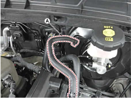
7.Disconnect the brake booster vacuum hose (A).
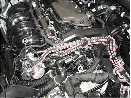
8.Disconnect the fuel hose (A) and PCSV (Purge Control Solenoid Valve) hose (B).
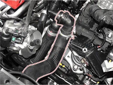
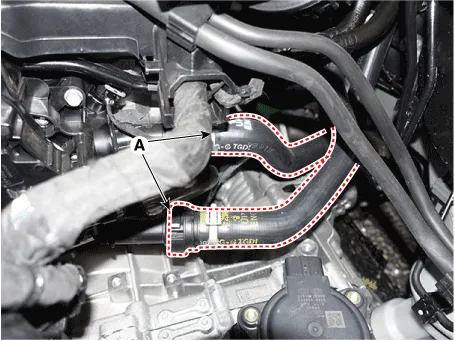
9.Disconnect the radiator upper hose quick connector (A).
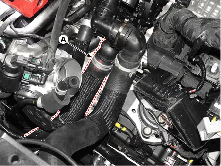
10.Disconnect the radiator lower hose quick connector (A).
11.Disconnect the heater hose (A).
12.Remove the cylinder head cover.(Refer to Cylinder Head Assembly - "Cylinder Head Cover")
13.Remove the timing chain cover.(Refer to Timing System - "Timing Chain Cover")
14.Remove the timing chain.(Refer to Timing System - "Timing Chain")
15.Remove the ITM (Integrated Thermostat management Module)(Refer to Cooling System - "ITM")
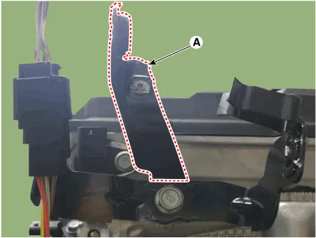
16.Remove the oxygen sensor connector bracket (A).
Tightening torque :7.8 - 11.7 N.m (0.8 - 1.2 kgf.m, 5.7 - 8.6 Ib.ft)
17.Remove the brake hose and pipe (A).
Tightening torque :7.8 - 9.8 N.m (0.8 - 1.0 kgf.m, 5.7 - 7.2 Ib.ft)
18.Remove the intake/exhaust CVVT and camshaft assembly.(Refer to Cylinder Head Assembly - "CVVT & Camshaft")
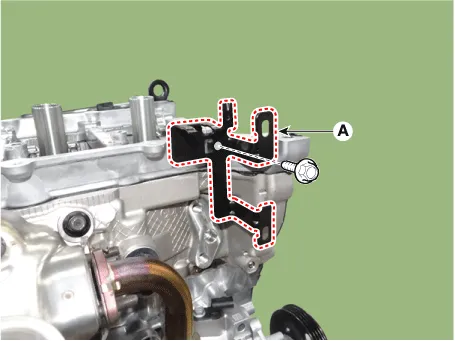
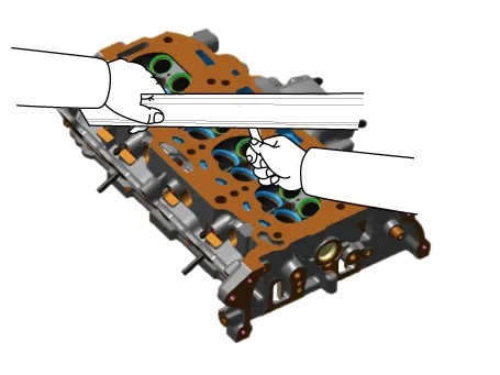
19.Remove the cam carrier (A).


• When removing the cam carrier, remove the cam carrier mounting bolt (A).
20.Remove the intake manifold.(Refer to Intake and Exhaust System - " Intake Manifold")
21.Remove the exhaust manifold.(Refer to Intake and Exhaust System - "Exhaust Manifold")
22.Remove the EGR cooler.(Refer to Intake and Exhaust System - "EGR Cooler")
23.Remove the EGR (Exhaust Gas Recirculation) control valve.(Refer to Engine Control / Fuel System - "EGR Control Valve")
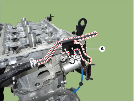
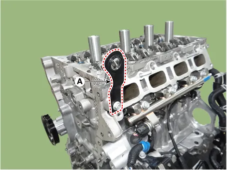
24.Remove the engine hanger (A).
Tightening torque :18.6 - 23.5 N.m (1.9 - 2.4 kgf.m, 13.7 - 17.3 Ib.ft)
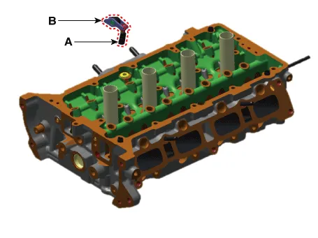
25.Remove the HLA (Hydraulic Lash Adjuster) and swing arm (B).
26.Remove the delivery pipe.(Refer to Engine Control/Fuel System – “Delivery Pipe”)
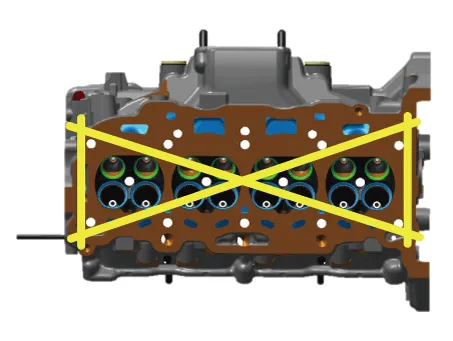
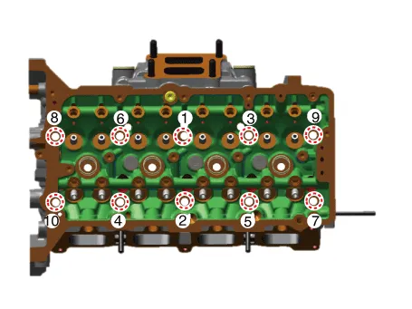
27.Loosen the cylinder head bolts and remove the cylinder head.
(1)Using a socket, remove the cylinder head bolts in several passes as shown in the belowillustration.
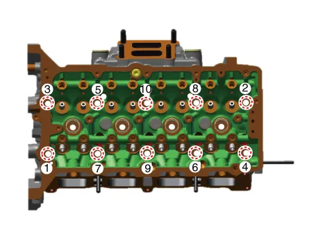

• Head warpage or cracking could result from removing bolts in an incorrect order.
• If the cylinder head bolts are loosened in the wrong order, the cylinder head may be warpedor broken.
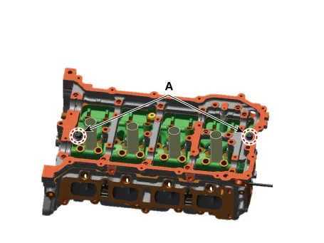
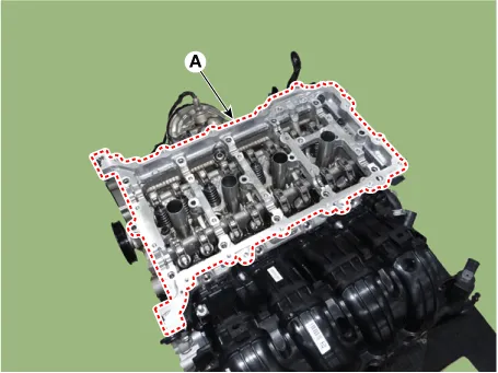
(2)Lift the cylinder head (A) from the cylinder block and place it on the wooden block.
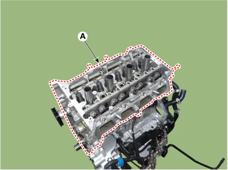

• Be careful not to damage the contact surfaces of the cylinder head and cylinder block.
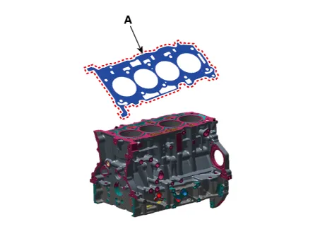
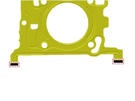
(3)Remove the cylinder head gasket (A).
1.Remove the valves.
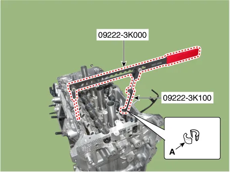
(1)Using the SST (09222-3K000, 09222-3K100), compress the valve spring and remove the valvespring retainer lock (A).
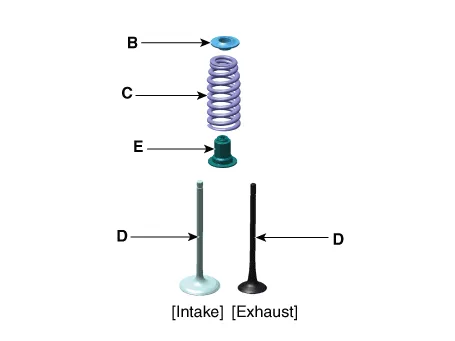
(2)Remove the spring retainer (B).
(3)Remove the valve spring (C).
(4)Remove the valve (D).
(5)Using long-nose pliers, remove the stem seal (E).

• Always use new valve stem seals.
• Be careful not to change the position of the intake valve and exhaust valve.
1.Using a precise steel square ruler and feeler gauge, measure the flatness of the contact surface of cylinder block and the manifolds.
Flatness of cylinder head gasket surfaceStandard : Less than 0.05 mm (0.0019 in.) / for total area Less than 0.02 mm (0.0007 in.) /for a section of 100 mm (3.9370 in.) X 100 mm (3.9370 in.)Flatness of manifold mounting surface (Intake/Exhaust)Standard : Less than 0.10 mm (0.0039 in.)
2.Inspect for cracks.Check the combustion chamber, intake ports, exhaust ports and cylinder block contact surfacesfor cracks. If cracked, replace the cylinder head.
1.Inspect the valve stem and valve guides.
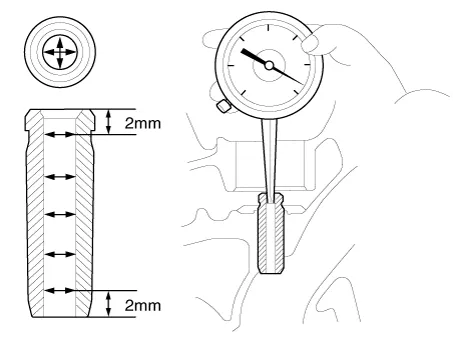
(1)Using a caliper gauge, measure the inside diameter of the valve guide.
Valve guide inner diameter (Intake/Exhaust) : 5.500 - 5.512 mm (0.21653 - 0.21700 in.)
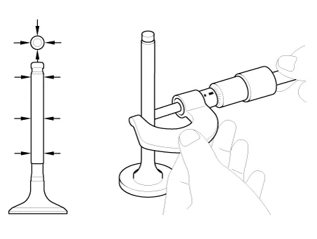
(2)Using a micrometer, measure the outer diameter of the valve stem.
Valve stem outer diameterIntake : 5.460 - 5.475 mm (0.21496 - 0.21555 in.)Exhaust : 5.453 - 5.465 mm (0.21468 - 0.21515 in.)
(3)Calculate the gap between the valve guide and the valve stem by subtracting the differencebetween the measured value of the valve guide inner diameter and the stem outer diameter.
Valve stem-to-guide clearanceIntake : 0.025 - 0.052 mm (0.0010 - 0.0020 in.)Exhaust : 0.035 - 0.059 mm (0.0014 - 0.0023 in.)
If the clearance is greater than maximum value, replace the valve or cylinder head.2.Inspect the valves.
(1)Check the angle of the valve face.
(2)Check the contact surface of the valve for wear. If the valve is excessively worn, replace thevalve.
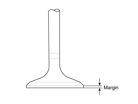
(3)Check the valve margin thickness.
Valve head thickness (Margin)[Standard]Intake : 0.8 mm(0.0314 in.)Intake : 0.8 mm(0.0314 in.)
(4)Check the valve length
Valve length[Standard]Intake : 108.378 mm (4.2668 in.)Exhaust : 119.875 mm (4.7195 in.)[Limit Value]Intake : 108.228 mm (4.2609 in.)Exhaust : 119.728 mm (4.7137 in.)
3.Inspect the valve seats.Check the valve seat for evidence of overheating and valve face contact condition. Replace thecylinder head if the valve seat is worn.Check the valve guide for wear. If the valve guide is worn, replace the cylinder head.
4.Inspect the valve springs.
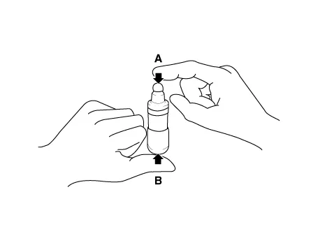
(1)Using a steel square ruler, measure the out-of-square of the valve spring.
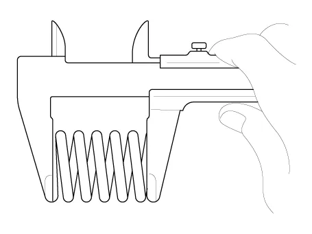
(2)Using a vernier calipers, measure the free length of the valve spring.
Valve springFree length : 52.51 mm (2.0673 in.)Squareness : Less than 1.5°
| Problem | Possible cause | Action | ||||||
| 1. Temporary noise when initial engine starting. | Normal | When the engine is stopped, the oil is leaking from the HLA, so the noise disappears when the oil pressure reaches steady state. | ||||||
| 2. Continuous noise when the engine is started after parking more than 48 hours | Oil leakage of the high pressure chamber in the HLA, allowing air to get in. | Noise will disappear within 15 minutes when engine runs at 2000 - 3000 rpm. If the noise doesn’t disappear, refer to step 7 below.
|

3. Continuous noise when the engine is first started right after removal and installation of the cylinder head.
Insufficient amount of oil in cylinder head oil passage.
4. Continuous noise when the engine is started after the excessive cranking of the engine by the starter motor or band
• Oil leakage of the high-pressure chamber in the HLA, allowing air to get in.
• Insufficient oil in the HLA
5. Continuous noise when the engine is running after changing the HLA
6. Continuous noise during idle after high engine speed
Engine oil level too high or too low
• Check oil level.
• Drain or add oil as necessary.
Excessive amount of air in the oil
Check oil supply system.
Deteriorated oil
Change the oil
7. Noise continues for more than 15 minutes
Low oil pressure
Check oil pressure and oil supply system of each part of engine.
Faulty HLA
Remove the cylinder head cover, and then inpect the HLA. If sponge symptom is detected, replace the HLA.

• Be aware of hot HLA.
* Sponge : It is a symptom that HLA can be pressed even by the back of the hand as air flows into the high pressure chamber in the HLA.

• Thoroughly clean all parts to be assembled.
• Before installing the parts, apply fresh engine oil to all sliding and rotating surfaces.
• Always use new valve stem seals.
1.Install the valve.
(1)After applying engine oil to the valve stem seal, install new valve stem seal (E) by using theSST(09222-4A000).

• Always use new valve stem seals.
• Incorrect installation of the seal could result in oil leakage through the valve guides.
(2)Apply engine oil to the entire outer circumferential surface of each valve stem and insert valve (D) into the valve guide.
(3)Install the valve spring (C).
(4)Install the spring retainer (B).


• Be careful not to change the position of the intake valve and exhaust valve.
(5)Using the SST (09222-3K000, 09222-3K100), compress the valve spring and install the valvespring retainer locks (A).


• Thoroughly clean all parts to be assembled.
• Always use new cylinder head and manifold gaskets.
• Always use new cylinder head bolts.
• The cylinder head gasket is a metal gasket. Take care not to bend it.
• Rotate the crankshaft to set the No.1 piston at TDC (Top Dead Center).
• Remove the oil, dust on the cylinder head and cylinder block surfaces where gasket is seatedto prevent scratches.
1.Install the cylinder head.
(1)Remove the hardening sealant, oil, cleaning residue, foreign materials remaining on thecylinder block and cylinder head.
(2)Apply liquid gasket on the top of the cylinder block.
Bead width : 2.0 - 3.0 mm (0.07 - 0.11 in.)Sealant : MS 721-40 AA or AA0

(3)Install the cylinder head gasket (A) on the cylinder block.


• Be careful not to change the mounting direction of the gasket.
(4)Apply liquid sealant on the top of the cylinder head gasket.
Bead width : 2.0 - 3.0 mm (0.07 - 0.11 in.)Sealant : MS 721-40 AA or AA0
(5)Carefully put the cylinder head (A) on the cylinder block to prevent damaging the headgasket.

2.Install new cylinder head bolts.
(1)Do not apply engine oil to the new cylinder head bolts.
(2)Tighten the cylinder head bolts in several passes.
Tightening torque :1st step : 32.3 - 36.2 N.m (3.3 - 3.7 kgf.m, 23.8 - 26.7 lb-ft)2nd step : 90 - 94°3rd step : 110 - 114°

• Do not reuse the cylinder head bolts.
• Do not apply engine oil to the cylinder head bolts.
• Remove the extruded sealant of the cylinder head and block within 5 minutes after assemblingcylinder head bolts.
3.Install the hydraulic lash adjuster (HLA) (A) and the swing arm (B).

4.Place the cam carrier on the cylinder head.
(1)Remove the hardening sealant, oil, cleaning residue, foreign materials gathered in the bottomof the cam carrier and on the top of the cylinder head.
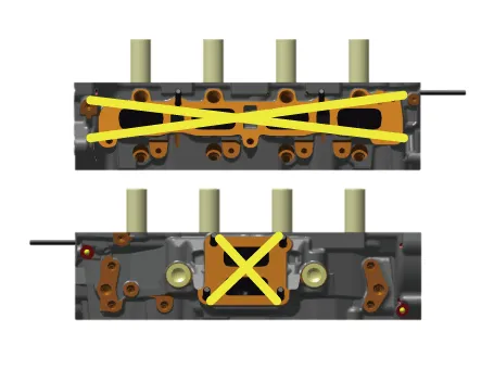
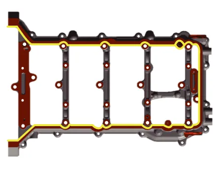
(2)Apply a continuous bead of liquid gasket to the bottom surface of the cam carrier, as shownin the illustration.
Bead width : 2.0 - 3.0 mm (0.07 - 0.11 in.)Sealant : MS 721-40 AA or AA0
(3)The dowel pins on the cam carrier and holes on the top of the cylinder head should be usedas a reference in order to assemble the cam carrier in exact position.
(4)Install the cam carrier (A).
Tightening torque :18.6 - 22.5 N.m (1.9 - 2.3 kgf.m, 13.7 - 16.6 lb-ft)

• Tighten the cam carrier mounting bolts when installing the cam carrier.


• Assemble the cam carrier within 5 minutes after applying sealant.
• Assemble the camshaft bearing cap within 5 minutes after assembling the cam carrier.(Refer to Cylinder Head Assembly - "CVVT & Camshaft")
• The engine running or pressure test should not be performed within 30 minutes afterassembling the cam carrier.
5.Installation is in the reverse order of removal.
6.Fill the coolant.(Refer to Cooling System - "Coolant")

• Coolant must be filled according to the ITM coolant filling method.
7.Fill the engine oil(Refer to Lubrication System - "Engine Oil")
 CVVT & Camshaft
- Description
[Electric E-CVVT]
Electric E-CVVT system is electric continuous variable valve timing
system. It is located on theintake camshaft of the engine and uses motor
rotation to control ...
 Cylinder Block
...
Other information:
Hyundai Tucson (NX4) 2022-2026 Owner's Manual: Interior Light Replacement
Map lamp, Rear room lamp
(LED type)
If the LED light does not operate, contact
an authorized HYUNDAI dealer for
replacement.
The LED light cannot be replaced as a
single unit. A skilled technician should
check or repair the LED light, for it may
damage related parts of the vehicle.
...
Hyundai Tucson (NX4) 2022-2026 Owner's Manual: Immobilizer indicator light
Without smart key
This indicator light illuminates:
When the vehicle detects the
immobilizer in the key with the
ignition switch in the ON position.
- At this time, you can start the
engine.
- The indicator light goes off after
starting the engine.
This indicator light bl ...
