Hyundai Tucson: Cylinder Head Assembly / CVVT & Camshaft
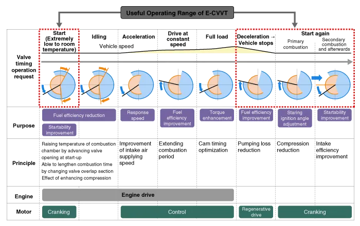

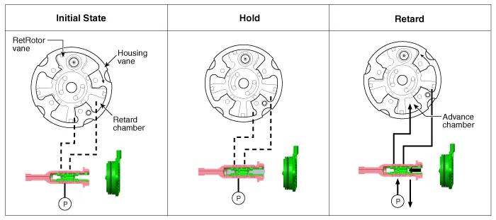
• The variable force solenoid (VFS) changes its force depending on the PWM duty to control thestroke of the OCV.
• It also controls the lock, unlock, advanced, retarded, and holding functions.
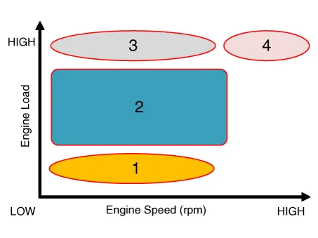
| (1) Low Speed / Low Load | (2) Part Load |
|
|
| (3) Low Speed / High Load | (4) High Speed / High Load |
|
|
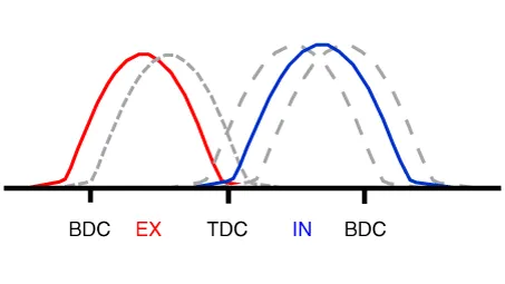

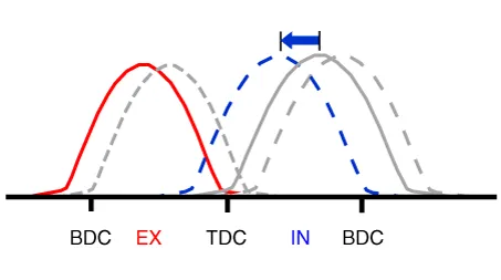
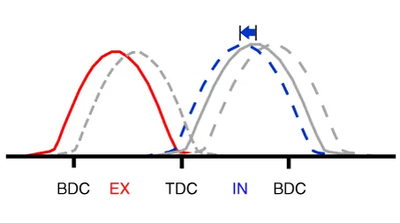
| Driving Condition | Exhaust Valve | Intake Valve | ||
| Valve Timing | Effect | Valve Timing | Effect | |
| (1) Low Speed /Low Load | Completely Advance | * Valve Under-lap * Improvement of combustion stability | Neutral | * Valve Under-lap * Improvement of combustion stability |
| (2) Part Load | Retard | * Reduction of HC | Retard | * Reduction of pumping loss by retarding the intake valve closing timing |
| (3) Low Speed /High Load | Completely Advance | * Reduction of pumping loss | Advance | * Improvement of volumetric efficiency |
| (4) High Speed /High Load | Completely Advance | * Reduction of pumping loss | Advance | * Improvement of volumetric efficiency |

• Be careful not to damage the parts located under the vehicle (floor under cover, fuel filter, fuel tank and canister) when raising the vehicle using the lift.(Refer to General Information - "Lift and Support Points")
1.Remove the timing chain.(Refer to Timing System - "Timing Chain")
2.Remove the high pressure fuel pump bracket (A).

3.Remove it by breaking the center of E-CVVT motor plug (A).
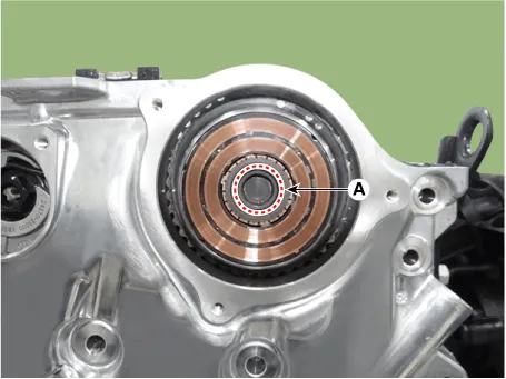

• Remove after 30 minutes of switching "OFF" the ignition to drain out the oil inside the E-CVVTmotor plug.
• Do not tilt the front of engine (timing chain cover side) downward as residual oil may flowout during E-CVVT motor plug removal.
• If oil flows out during E-CVVT motor plug removal, wipe off immediately and block the motorshaft inlet with a clean towel.
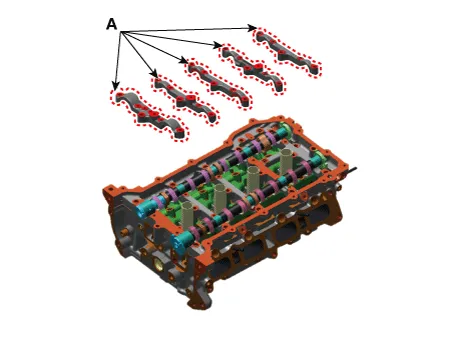
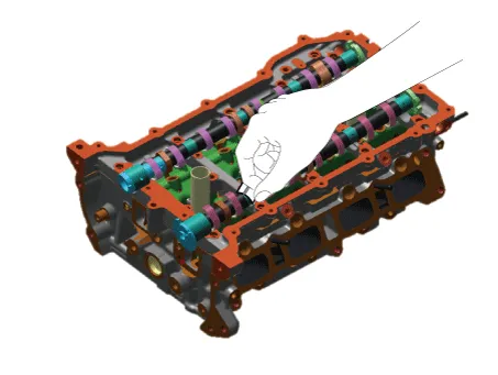
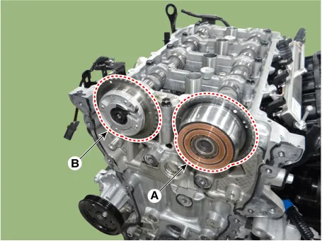
4.Remove the intake E-CVVT assembly (A) and exhaust CVVT assembly (B).


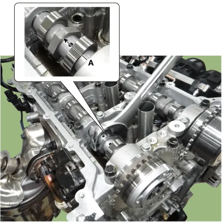
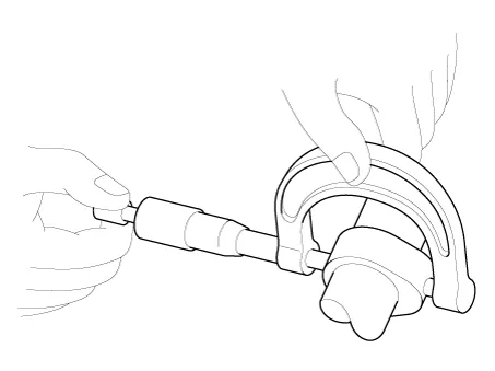
• When removing the CVVT assembly bolt, hold the camshaft (A) with a wrench to prevent thecamshaft from rotating.
5.Remove the Camshaft.
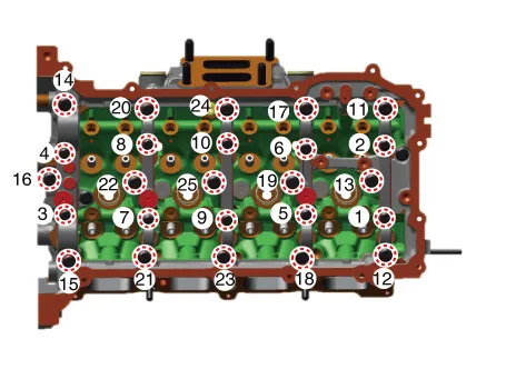
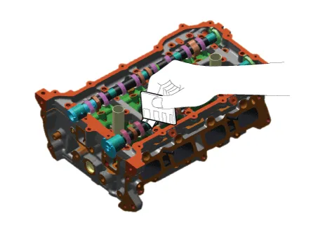
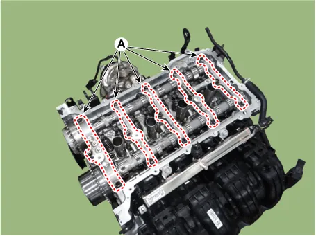
(1)Remove the Camshaft bearing cap (A).

• Be careful not to change the position and direction of the camshaft bearing caps.

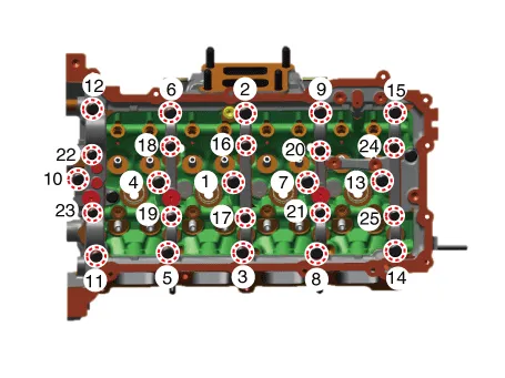
• Remove the camshaft bearing caps in the sequence shown below.
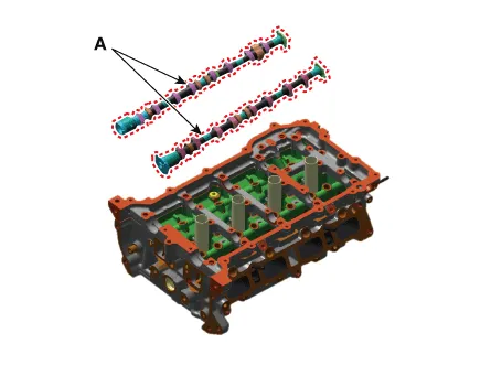
(2)Remove the camshaft (A).
1.Remove the timing chain.(Refer to Timing System - "Timing Chain")
2.Remove the high pressure fuel pump bracket (A).

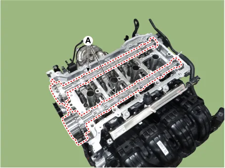
3.Remove the intake/exhaust CVVT and camshaft assembly.
(1)Remove the Camshaft bearing cap (A).


• Be careful not to change the position and direction of camshaft bearing caps.

• Remove the camshaft bearing caps in the sequence shown.
(2)Remove the intake/exhaust CVVT and camshaft assembly (A).
Camshaft
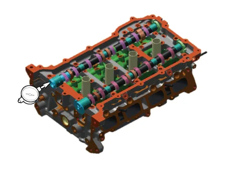
1.Inspect the cam lobe height.Using a micrometer, measure the cam lobe height.
Intake : 39.50 mm (1.5551in)Exhaust : 37.60 mm (1.4803in)
2.Inspect the camshaft journal clearance.
(1)Clean the bearing caps and camshaft journals.
(2)Place the camshafts on the cam carrier.
(3)Lay a strip of plastic gauge across each of the camshaft journal.
(4)Install the camshaft bearing caps (A) and tighten the bolts to the specified torque.
Tightening torque :Step 1M6 : 4.9 - 7.8 N.m (0.5 - 0.8 kgf.m, 3.6 - 5.7 lb-ft)M8 : 9.8 - 11.7 N.m (1.0 - 1.2 kgf.m, 7.2 - 8.6 lb-ft)Step 2M6 : 11.7 - 13.7 N.m (1.2 - 1.4 kgf.m, 8.6 - 10.1 lb-ft)M8 : 18.6 - 22.5 N.m (1.9 - 2.3 kgf.m, 13.7 - 16.6 lb-ft)


• Do not turn the camshaft.


• Do not turn the camshaft.
(5)Remove the camshaft bearing caps (A).

(6)Measure the plastic gauge at its widest point.
Camshaft cap oil clearance[Specified value]No.1 journal : 0.037 - 0.065 mm (0.00114 - 0.00224 in.)No.2, 3, 4, 5 journal : 0.037 - 0.067 mm (0.00145 - 0.00263 in.)
(7)Completely remove the plastic gauge.
(8)Remove the camshaft.
3.Inspect the camshaft end play.
(1)Install the camshaft.
(2)Using a dial gauge, measure the end play while moving the camshaft back and forth.
Camshaft end play[Standard value] : 0.09 - 0.23 mm (0.0035 - 0.0090 in.)
1.Install the intake and exhaust CVVT & camshaft assembly.
(1)Install the intake and exhaust CVVT & camshaft assembly (A).


• When installing the camshaft, apply engine oil to the cam carrier journal and then apply engineoil to the camshaft journal after installing the camshaft.
(2)Install the camshaft bearing caps (A) and tighten the bolts to the specified torque.
Tightening torque :Step 1M6 : 4.9 - 7.8 N.m (0.5 - 0.8 kgf.m, 3.6 - 5.7 lb-ft)M8 : 9.8 - 11.7 N.m (1.0 - 1.2 kgf.m, 7.2 - 8.6 lb-ft)Step 2M6 : 11.7 - 13.7 N.m (1.2 - 1.4 kgf.m, 8.6 - 10.1 lb-ft)M8 : 18.6 - 22.5 N.m (1.9 - 2.3 kgf.m, 13.7 - 16.6 lb-ft)

• Be careful not to change the position and direction of camshaft bearing caps.

• Install the camshaft bearing caps in the sequence below.
2.Install the high pressure fuel pump bracket (A).
Tightening torque : 18.6 - 23.5 N.m (1.9 - 2.4 kgf.m, 13.7 - 17.3 Ib.ft)

3.Install the timing chain.(Refer to Timing System - "Timing Chain")
1.Install the camshaft.
(1)Install the camshaft (A).


• When installing the camshaft, apply engine oil to the cam carrier journal and then apply engineoil after installing the camshaft.
(2)Install the camshaft bearing caps (A).
Tightening torque :Step 1M6 : 4.9 - 7.8 N.m (0.5 - 0.8 kgf.m, 3.6 - 5.7 lb-ft)M8 : 9.8 - 11.7 N.m (1.0 - 1.2 kgf.m, 7.2 - 8.6 lb-ft)Step 2M6 : 11.7 - 13.7 N.m (1.2 - 1.4 kgf.m, 8.6 - 10.1 lb-ft)M8 : 18.6 - 22.5 N.m (1.9 - 2.3 kgf.m, 13.7 - 16.6 lb-ft)


• Be careful not to change the position and direction of the camshaft bearing caps.

• Install the camshaft bearing caps in the sequence shown below.

2.Install the intake E-CVVT assembly (A) and exhaust CVVT assembly (B).
Tightening torqueIntake E-CVVT Assembly :73.5 - 83.3 N.m (7.5 - 8.5 kgf.m, 54.2 - 61.4 lb-ft)Exhaust CVVT Assembly :22.5 - 26.4 N.m (2.3 - 2.7 kgf.m, 16.6 - 19.5 lb-ft) + 28 - 32°

• When installing the CVVT assembly bolt, hold the camshaft (A) with a wrench to prevent thecamshaft from rotating.


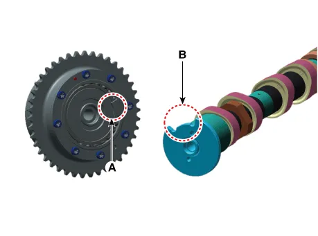
• Tighten the bolt when the E-CVVT stopper (A) is matched with the camshaft slot (B).
3.Install the high pressure fuel pump bracket (A).
Tightening torque : 18.6 - 23.5 N.m (1.9 - 2.4 kgf.m, 13.7 - 17.3 Ib.ft)
4.Install the timing chain.(Refer to Timing System - "Timing Chain")
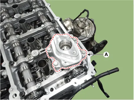
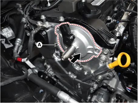
5.Clean the E-CVVT motor plug mounting surface (A) with oil cleaner.


• If the surface is not cleaned, E-CVVT motor plug may be separated due to diminishedseparation force from residual oil.
• When spraying oil cleaner, block around the motor shaft inlet and rotor gap with a clean towelto prevent inflow of oil from flowing into the rotor gap.
6.When reusing the E-CVVT cover, inspect the below items.
(1)If there is sign of leakage from inside the E-CVVT cover, replace it with a new one.
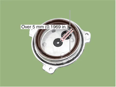
(2)Check the connector brush wear condition.
Specification : Over 5 mm (0.1969 in.)
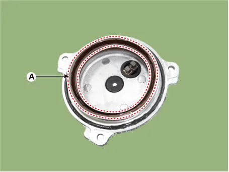
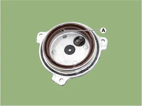
(3)Check for damaged oil seal (A) and replace any damaged E-CVVT cover with a new one.
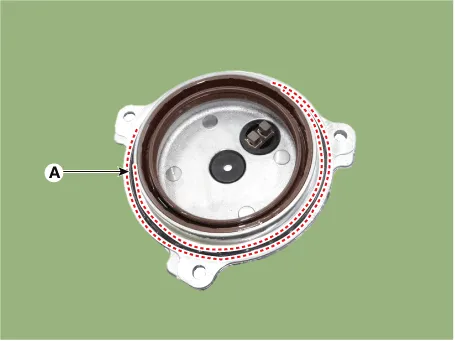
(4)After inspecting E-CVVT, if no problem is found, replace the o-ring (A) with a new one.
7.Install the E-CVVT cover.
(1)Apply engine oil to the oil seal lip (A).

• When applying oil, keep the connector brush (A) clean from foreign materials.
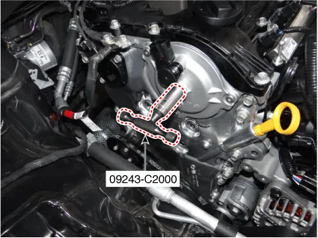
(2)Insert SST(09243-C2000) into the E-CVVT motor shaft.
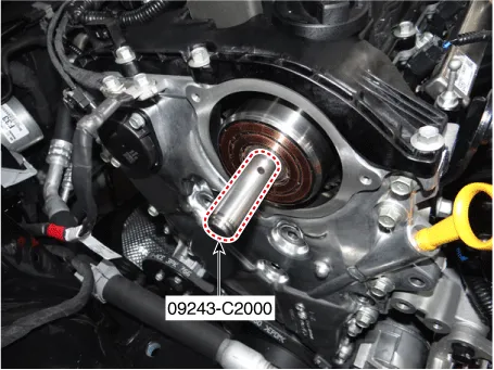

• Correctly mount SST onto the motor shaft.
(3)Slowly push the E-CVVT cover (A) until it is flushed with the timing chain cover surface.

• Installing the E-CVVT cover without SST may cause oil leakage inside the E-CVVT motor due todamaged or separated E-CVVT oil seal.
(4)Pre-tighten the bolts in the below sequence, and then remove the SST(09243-2C000).
Tightening torque : 0.9 - 1.9 N.m (0.1 - 0.2 kgf.m, 0.7 - 1.4 Ib.ft)
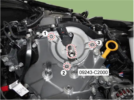
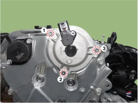
(5)Tighten the bolts to the specified torque in the sequence below.
Tightening torque : 9.8 - 11.7 N.m (1.0 - 1.2 kgf.m, 7.2 - 8.6 Ib.ft)
8.Install the E-CVVT plug.
(1)By using SST(09243-C2000), insert the plug into the E-CVVT cover hole.
(2)Mount the stopper of SST(09243-C2000) so that it sits at the end of E-CVVT motor shaft.
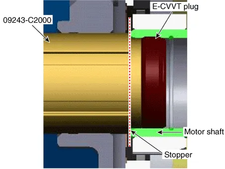
9.Inspect the pressed depth of E-CVVT plug.
(1)By using a steel ruler, measure the distance from E-CVVT cover center boss to the end of motor shaft (â‘ ).
(2)By using a steel ruler, measure the distance from E-CVVT cover center boss to the end of E-CVVT plug (②).
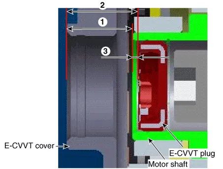
(3)Calculate the pressed depth (③) of motor plug.If out of specification, reinstall after replacing the E-CVVT plug with a new one.
Pressed depth : ③ = ② - ①Specification : 1.1 - 2.1 mm (0.0433 - 0.0826 in.)
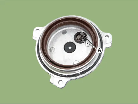
10.Insert the E-CVVT cover plug so that the protrusion reach to E-CVVT cover groove correctly.
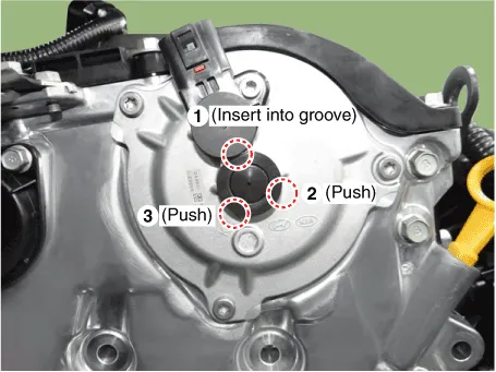

• Check how much protrude after installing the E-CVVT cover plug.

• Be careful that the plug is not inserted inside E-CVVT cover beyond the regulated range.

• When replacing or reinstalling the electronic E-CVVT assembly, make sure to reset the value oflearning using additional function menu of diagnostic tool.(Refer to Engine Control/Fuel System - "Electronic E-CVVT Motor")additional function menu of diagnostic tool.
 Cylinder Head Cover
- Removal
• Use fender covers to avoid damaging painted surfaces.
• To avoid damage, unplug the wiring connectors carefully while holding the connector portion.
...
 Cylinder Head
- Removal
• Be careful not to damage the parts located under the vehicle
(floor under cover, fuel filter, fuel tank and canister) when raising
the vehicle using the lift.( ...
Other information:
Hyundai Tucson (NX4) 2022-2026 Service Manual: DC DC converter
- Description
Due to the considerably more frequent occurrence of starting
operations, the electrical load that occurs often leads to voltage dips
in the vehicle network.In order to stabilize the power supply for
certain voltage-sensitive electrical components, a DC/DC converter is
used i ...
Hyundai Tucson (NX4) 2022-2026 Service Manual: Intake Manifold
- Components
1. Intake manifold2. Intake manifold gasket3. Intake manifold stay4. Electronic Throttle Contorl (ETC)5. Electronic Throttle Contorl (ETC) gasket6. Purge Control Solenoid Valve (PCSV) & Bracket7. Vacuum hose & Pipe
- Removal and Installation
• ...
