Hyundai Tucson: Automatic Transaxle Control System / Speed Sensor
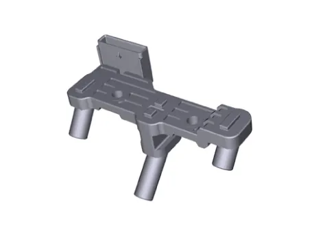
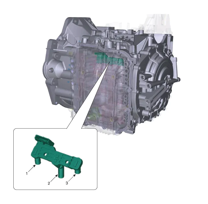
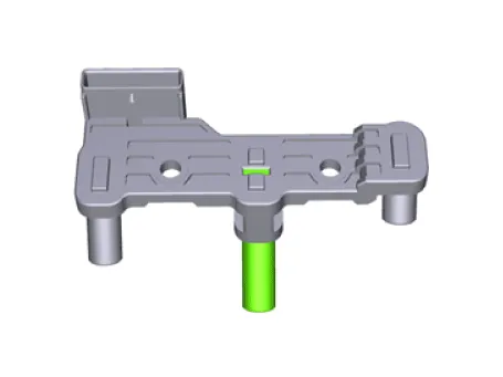
1. Input speed sensor
2. Output speed sensor
3. Middle speed sensor
| Item | Specification |
| Type | Hall effect sensor |
| Operating condition (˚C)˚F | (-40 to 150) -40 to 302 |
| Output voltage (V) | High : 1.18 - 1.68 |
| Low : 0.59 - 0.84 |

• Refer to the DTC manual for the check procedure.

• When the solenoid valve Diagnostic Trouble Codes (DTC) is on, perform the following procedure to replace it.
• Automatic transaxle is composed of delicate components. Be careful not to cause any damage on the component in the course of assembly and disassembly.
• Maintain clean condition so that foreign substance does not get into the automatic transaxle.
• Use a coated apron, latex gloves, and stainless tray to prevent foreign substance from getting into the transaxle.
• Automatic transaxle fluid (ATF) can be reused. Collect it using a clean 10-liter beaker.
• Be careful not to damage the parts located under the vehicle (floor under cover, fuel filter, fuel tank and canister) when raising the vehicle using the lift.(Refer to General Information - "Lift and Support Points")
1.Turn ignition switch OFF and disconnect the negative (-) battery cable.
2.Remove the air cleaner assembly.(Refer to Engine Mechanical System - "Air cleaner")
3.Loosen the wiring bracket mounting bolt (A).

4.Remove the engine room under cover.(Refer to Engine Mechanical System - "Engine Room Under Cover")
5.Remove the drain plug (A) and reinstall the drain plug after draining ATF totally.
Drain plug tightening torque :33.3 - 43.1 N.m (3.4 - 4.4 kgf.m, 24.6 - 31.8 lb-ft)
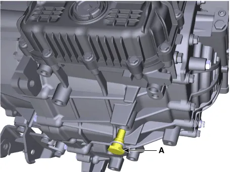

• Replace the gasket before reinstalling the drain plug.
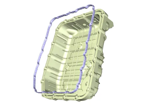
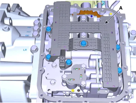
6. Loosen the mounting bolts (A) of the valve body cover.
Tightening torque : 11.8 - 13.7 N.m (1.2 - 1.4 kgf.m, 8.7 - 10.1 lb-ft)


• Be careful when removing the valve body cover because the remaining ATF remains in the valve body cover.

• Replace the gasket (A) before reinstalling the valve body cover.
• After the installation, start the engine and then check if there are any leakages from the valve body cover.
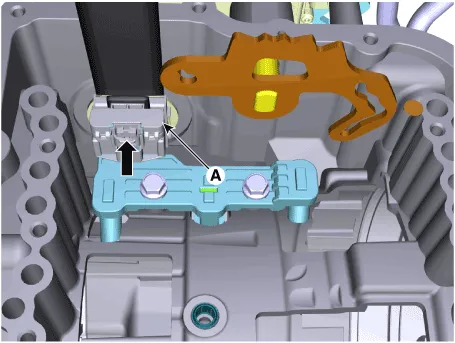
7. Loosen the bolts and then removing the main harness (A).
Tightening torque : 9.8 - 11.8 N.m (1.0 - 1.2 kgf.m, 7.2 - 8.7 lb-ft)
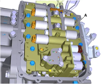
8.Loosen the bolts and then removing the valve body assembly (A).
Tightening torque : (A) 9.8 - 11.8 N.m (1.0 - 1.2 kgf.m, 7.2 - 8.7 lb-ft)

• Attach the manual pin (B) to the detent lever (A) and assemble the valve body.
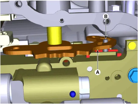
9.Disconnect the speed sensor connector (A).
10.Remove the speed sensor (B).
Tightening torque : 9.8 - 11.8 N.m (1.0 - 1.2 kgf.m, 7.2 - 8.7 lb-ft)
1.To install, reverse the removal procedure.
2.Inject the automatic transaxle oil and inspect the oil level.(Refer to Automatic Transaxle System - "Automatic Transaxle Fluid")

• After ATF level check or exchange, be sure to remove residual ATF on transaxle case.(Be especially sure to remove residual ATF between automatic transaxle case and valve body cover)
• After installing the valve body cover, make sure to check the oil leakage at the connection area with the engine ON.
3.After ATF level check or exchange, be sure to remove residual ATF on transaxle case.(Be especially sure to remove residual ATF between automatic transaxle case and valve body cover)
4.Check for leakage of coolant or fluid from hose connection during engine start.
 Transaxle Oil Temperature Sensor
- Description
• Transaxle oil temperature sensor monitors the automatic transaxle fluid's temperature and conveys the readings to TCM.
• It is an NTC (Negative Thermal Coefficient) sensor w ...
 Position Sensor
- Specification
Position Sensor
▷ SpecificationsItemSpecification
Output typeNon-Contact type (2 channels, PWM signal output)
Input power (V)4.5 - 5.5
- Description
Output position sig ...
Other information:
Hyundai Tucson (NX4) 2022-2025 Service Manual: Components and Components Location
- Component Location
1. Start Stop Button(SSB)2. FOB Key3. Liftgate open button4. Interior antenna 15. Interior antenna 26. Intergrated Body Control Unit (IBU)7. Liftgate antenna8. Door handle & door antenna9. Front bumper antenna10. Rear Bumper antenna11. Door antenna
...
Hyundai Tucson (NX4) 2022-2025 Service Manual: CVVT & Camshaft
- Description
[Electric E-CVVT]
Electric E-CVVT system is electric continuous variable valve timing
system. It is located on theintake camshaft of the engine and uses motor
rotation to control the rotation angle of camshaftrelative to the
rotation of crankshaft regardless of engine pressur ...
