Hyundai Tucson: Surround View Monitor (SVM) / Description and Operation

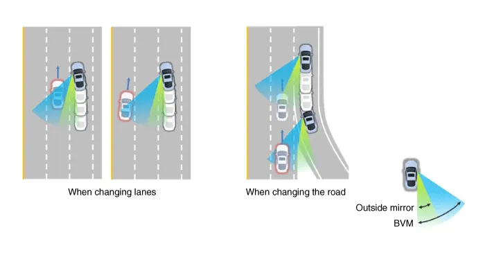
The BVM system provides a driver a more comprehensive view which is not usually visible by the side mirrors in certain situations like swithing drive lanes. The system helps to avoid any blind spot mishaps.
– The rear side view is displayed in the cluster screen when the turning lights are in operation as the turn signal light switch goes up and down by the driver.
– The SVM also provides an edited view of the left side/ right side without adding more cameras.
– It helps minimize the distraction of the driver by displaying the rear side view that is usually hard to see.

• The video will be played even though the side mirrors are folded. But it does not provide a proper view of the surroundings.
• The video quality may be lower than the SVM video as the size of the original image has to be adjusted to fit the cluster.
• The screen may temporarily fades out with changes in light conditions during daytime or with a sunrise or a sunset. Or when the car enters the tunnel.
• The view of the surrounding objects provided by the system may look far away than views that are obtained by the side mirrors.
• The brightness of the rear side video may change due to a mode switching delay of the SVM/BVM.
1.Display Vehicles Surrounding in VideoThe surrounding area video display function displays the 360 degrees video image captured through 4 cameras to the driver through the Head controller Screen while the vehicle is moving at low speed or going reverse. The SVM System displays total of 8 video modes for displaying surrounding video based on the vehicle driving state and the driver's selection.
2.Guide Line Indication & Steering Wheel Synchronized FeatureThe Guide Line Indication & Steering Wheel Synchronized Feature is the function that assists the driver in parking by synchronizing the steering wheel with the rear view video display marked with a guide line to help anticipate the direction of the vehicle going reverse.
3.Front/Rear Object Warning (Obstacle Detection Feature) The system receives obstacle warning signal from the PAS or SPAS sensors mounted on the front/rear of the vehicle and displays the obstacle location on the SVM Head Unit Screen.
4.Tolerance Compensation (including A/S)Manual Tolerance Compensation Software is embedded in the SVMECM to compensate the SVM deviation that may occur due to assembly line installation tolerance. You must first setup proper work environment in order to perform correct tolerance compensation.
– Initial Entry: When the rear and front mode view in SVM mode is displayed on the screen for the first time
– Re-entry: When switching from SVM mode to another mode, without turning off SVM, and returning to the previous mode (e.g. Rear → Front → Rear: Re-enter rear mode / Front → Rear → Front: Re-enter front mode)
| Switch mode | Vehicle speed | Gear | SVM Switch | Display view |
| Rear → Front | below 15 kph | R Range or P Range excluded | ON | Initial Entry: Front view set in the initial view mode option |
| Re-entry: The last view mode displayed in the previous front mode | ||||
| Front → Rear | Irrelevant | Reverse Gear | Irrelevant | Initial Entry: Rear view set in the initial view mode option |
| Re-entry: The last view mode displayed in the previous rear mode |
| OFF Mode | Vehicle speed | Gear | SVM Switch | Notes |
| Front mode | over 20 kph | R Range or P Range | OFF | If any of the three conditions are satisfied |
| Rear mode | Irrelevant | Except R gear | Irrelevant | If any of the two conditions are satisfied |
| Option | Function | Default setting |
| Guideline steering interlocking | Interlocks with steering to display the driving direction of the vehicle during parking. | Classification code |
| Close range warning indicator | Indicates front and rear obstacle detection | Classification code |
| Initial view mode setting | Default view displayed when entering SVM mode | Front + around view |
| Rear + around view |
1.View modes for guideline steering interlocking indications
| Mode | View | Notes |
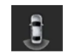
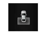
| Rear | Rear wide view + Top view |
|
| Rear top view + Top view |
| |
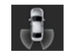
| Rear corner view + Top view |
|
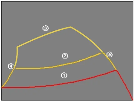
2.Specifications for guideline steering interlocking trace lines
| Number | Distance | Color |
| ① | 0.5 m | Red |
| ② | 1 m | Yellow |
| ③ | 3 m | Yellow |
| ④ | Bumper left side end + 0.3 m | Yellow |
| ⑤ | Bumper right side end + 0.3 m | Yellow |
3.Indications for neutral trace lines If the steering angle is neutral, the neutral trace line is indicated in blue, which shows the expected movement trace of the car. This line is displayed with the guideline steering interlocking trace line and is also a fixed line that is not interlocked with the steering angle operation.
1.Camera input
| Category | Specification | |
| Angle of view | Horizontal | 192˚ |
| Vertical | 137˚ | |
| Provided function | Original wide angle image is provided | |
| (No additional functions) | ||
| Applied position | Applied to front/rear/left/right cameras | |
2.SVM image displayThe images received from the 4 cameras mounted on the vehicle go through the image distortion correction logic and the image merging process.H/UNIT displays these images toghether with other additional features such as the parking guidelines linked with steering wheel on the AVN screen.
3.Parking/view buttonIt is used as a control input signal to operate the front view mode function with the ignition switch ON.
4.Ignition inputSVM controller displays the image only in the IGN1 ON and limits the image display with the SVM OFF in the IGN1 OFF.SVM controller uses the signal which is input to the IGN pin or B-CAN message routed from the IGPM (gateway) to C-CAN to judge the IGN1 ON/OFF.
5.Chassis CAN input (C_CAN)SVM controller receives the vehicle state information through the C_CAN to determine the operation of SVM major functions.
6.Multimedia CAN input/outputRelevant information is processed by receiving the M-CAN signal routed from the IGPM (gateway) to C-CAN.The routed M-CAN signal communication aims to transmit and receive the below information.

 Components and Components Location
- Components
...
Other information:
Hyundai Tucson (NX4) 2022-2025 Service Manual: Engine Control Module (ECM)
- ECM Connector and Terminal Function
ECM Terminal Function
Connector [A]
Pin NoDescriptionConnected to
1ECM GroundChassis Ground
2E-CVVT Motor [-] ControlE-CVVT Motor
3E-CVVT Motor [+] ControlE-CVVT Motor
4E-CVVT Relay PowerE-CVVT Relay
5-
6Sensor Power (+5V)Throttle Position Sensor ...
Hyundai Tucson (NX4) 2022-2025 Service Manual: Rear Door Window Glass
- Components Location
1. Rear door window glass
- Replacement
1.Remove the rear door trim.(Refer to Rear Door - "Rear Door Trim")
2.Remove the rear door belt outside weatherstrip.(Refer to Rear Door - "Rear Door Belt Outside Weatherstrip")
3.Remove the rear door belt inside weather ...
