Hyundai Tucson: Engine Control System / Engine Control Module (ECM)
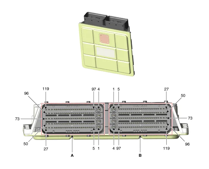
ECM Terminal Function
| Pin No | Description | Connected to |
| 1 | ECM Ground | Chassis Ground |
| 2 | E-CVVT Motor [-] Control | E-CVVT Motor |
| 3 | E-CVVT Motor [+] Control | E-CVVT Motor |
| 4 | E-CVVT Relay Power | E-CVVT Relay |
| 5 | - | |
| 6 | Sensor Power (+5V) | Throttle Position Sensor (TPS) |
| 7 | - | |
| 8 | - | |
| 9 | - | |
| 10 | Oil Temperature Sensor (OPTS) Signal Input | Oil Pressure & Temperature Sensor (OPTS) |
| 11 | Oil Pressure Sensor (OPTS) Signal Input | |
| 12 | - | |
| 13 | Sensor Ground | Engine Coolant Temperature Sensor (ECTS) #3 (Cylinder Block Side) |
| 14 | Engine Coolant Temperature Sensor (ECTS) #3 Signal Input | Engine Coolant Temperature Sensor (ECTS) #3 (Cylinder Block Side) |
| 15 | Intake Air Temperature Sensor (IATS) Signal Input | Intake Air Temperature Sensor (IATS) |
| 16 | - | |
| 17 | - | |
| 18 | - | |
| 19 | - | |
| 20 | - | |
| 21 | - | |
| 22 | - | |
| 23 | - | |
| 24 | - | |
| 25 | ECM Ground | Chassis Ground |
| 26 | - | |
| 27 | - | |
| 28 | - | |
| 29 | Throttle Position Sensor (TPS) #1 Signal Input | Throttle Position Sensor (TPS) #1 |
| 30 | Throttle Position Sensor (TPS) #2 Signal Input | Throttle Position Sensor (TPS) #2 |
| 31 | - | |
| 32 | - | |
| 33 | Sensor Ground | Oil Pressure & Temperature Sensor (OPTS) |
| 34 | - | |
| 35 | Engine Coolant Temperature Sensor (ECTS) #1 Signal Input | Engine Coolant Temperature Sensor (ECTS) #1 (ITM Side) |
| 36 | Engine Coolant Temperature Sensor (ECTS) #2 Signal Input | Engine Coolant Temperature Sensor (ECTS) #2 (Water Pump Side) |
| 37 | Camshaft Position Sensor (CMPS) [Bank 1 / Exhaust] Signal Input | Camshaft Position Sensor (CMPS) [Bank 1 / Exhaust] |
| 38 | Camshaft Position Sensor (CMPS) [Bank 1 / Intake] Signal Input | Camshaft Position Sensor (CMPS) [Bank 1 / Intake] |
| 39 | - | |
| 40 | - | |
| 41 | - | |
| 42 | - | |
| 43 | - | |
| 44 | - | |
| 45 | - | |
| 46 | - | |
| 47 | - | |
| 48 | ECM Ground | Chassis Ground |
| 49 | - | |
| 50 | - | |
| 51 | Knock Sensor (KS) Signal Input | Knock Sensor (KS) |
| 52 | Sensor Ground | |
| 53 | Sensor Ground | Throttle Position Sensor (TPS) |
| 54 | - | |
| 55 | EGR Valve Feedback Signal Input | EGR Valve |
| 56 | - | |
| 57 | - | |
| 58 | Sensor Ground | Engine Coolant Temperature Sensor (ECTS) #1 (ITM Side) |
| 59 | Sensor Ground | Engine Coolant Temperature Sensor (ECTS) #2 (Water Pump Side) |
| 60 | Sensor Ground | Manifold Absolute Pressure Sensor (MAPS) |
| Intake Air Temperature Sensor (IATS) | ||
| 61 | Sensor Ground | Camshaft Position Sensor (CMPS) [Bank 1 / Exhaust] |
| 62 | Sensor Ground | Camshaft Position Sensor (CMPS) [Bank 1 / Intake] |
| 63 | - | |
| 64 | - | |
| 65 | - | |
| 66 | - | |
| 67 | - | |
| 68 | - | |
| 69 | - | |
| 70 | - | |
| 71 | - | |
| 72 | - | |
| 73 | - | |
| 74 | NERNST Cell Voltage | Heated Oxygen Sensor (HO2S) [Bank 1 / Sensor 1] |
| 75 | VS-/IP- (Virtual Ground) | Heated Oxygen Sensor (HO2S) [Bank 1 / Sensor 2] |
| 76 | Rc (Correction Resistance) | Heated Oxygen Sensor (HO2S) [Bank 1 / Sensor 1] |
| 77 | Sensor Ground | Brake Booster Vacuum Pressure Sensor (BBVPS) |
| 78 | Sensor Ground | EGR Valve |
| 79 | - | |
| 80 | - | |
| 81 | Rail Pressure Sensor (RPS) Signal Input | Rail Pressure Sensor (RPS) |
| 82 | - | |
| 83 | Sensor Ground | Rail Pressure Sensor (RPS) |
| 84 | Sensor Ground | Crankshaft Position sensor (CKPS) |
| 85 | - | |
| 86 | - | |
| 87 | - | |
| 88 | - | |
| 89 | - | |
| 90 | - | |
| 91 | - | |
| 92 | EGR Valve Motor [+] Control | EGR Valve Motor |
| 93 | ETC Motor [+] Control | ETC Motor |
| 94 | - | |
| 95 | - | |
| 96 | ITM Motor [+] Control | ITM Motor |
| 97 | VG Virtual Ground | Heated Oxygen Sensor (HO2S) [Bank 1 / Sensor 1] |
| 98 | Heated Oxygen Sensor (HO2S) [Bank 1 / Sensor 2] Signal Input | Heated Oxygen Sensor (HO2S) [Bank 1 / Sensor 2] |
| 99 | Heated Oxygen Sensor (HO2S) [Bank 1 / Sensor 1] (V_IP) | Heated Oxygen Sensor (HO2S) [Bank 1 / Sensor 1] |
| 100 | Brake Booster Vacuum Pressure Sensor (BBVPS) Signal Input | Brake Booster Vacuum Pressure Sensor (BBVPS) |
| 101 | Sensor Power (+5V) | Oil Pressure & Temperature Sensor (OPTS) |
| 102 | Sensor Power (+5V) | Camshaft Position Sensor (CMPS) [Bank 1 / Exhaust] |
| Brake Booster Vacuum Pressure Sensor (BBVPS) | ||
| EGR Valve | ||
| 103 | Sensor Power (+5V) | Rail Pressure Sensor (RPS) |
| 104 | Sensor Power (+5V) | Crankshaft Position sensor (CKPS) |
| Manifold Absolute Pressure Sensor (MAPS) | ||
| Intake Air Temperature Sensor (IATS) | ||
| Camshaft Position Sensor (CMPS) [Bank 1 / Intake] | ||
| 105 | Manifold Absolute Pressure Sensor (MAPS) Signal Input | Manifold Absolute Pressure Sensor (MAPS) |
| 106 | - | |
| 107 | Crankshaft Position sensor (CKPS) Signal Input | Crankshaft Position sensor (CKPS) |
| 108 | - | |
| 109 | - | |
| 110 | - | |
| 111 | - | |
| 112 | - | |
| 113 | - | |
| 114 | - | |
| 115 | EGR Valve Motor [-] Control | EGR Valve Motor |
| 116 | ETC Motor [-] Control | ETC Motor |
| 117 | - | |
| 118 | - | |
| 119 | ITM Motor [-] Control | ITM Motor |
| Pin No | Description | Connected to |
| 1 | Battery Power (B+) | Main Relay |
| 2 | Battery Power (B+) | Main Relay |
| 3 | Battery Power (B+) | Main Relay |
| 4 | ECM Ground | Chassis Ground |
| 5 | Battery Power (B+) | Main Relay |
| 6 | P-CAN (High) | Other control module, Data Link Connector (DLC) |
| 7 | P-CAN (Low) | Other control module, Data Link Connector (DLC) |
| 8 | - | |
| 9 | - | |
| 10 | Sensor Power (+5V) | Accelerator Pedal Position Sensor (APS) #2 |
| 11 | Sensor Power (+5V) | Mass Air Flow Sensor (MAFS) |
| ITM Motor and Position Sensor | ||
| 12 | Sensor Power (+5V) | Accelerator Pedal Position Sensor (APS) #1 |
| 13 | Mass Air Flow Sensor (MAFS) Signal Input | Mass Air Flow Sensor (MAFS) |
| 14 | - | |
| 15 | - | |
| 16 | Vehicle Speed Signal Input | ABS Module |
| 17 | Ignition Feedback 'A' (Cylinder #4) Signal Input | Ignition Coil (Cylinder #4) |
| 18 | Ignition 'D' (Cylinder #3) Signal Input | Ignition Coil (Cylinder #3) |
| 19 | - | |
| 20 | - | |
| 21 | Variable Oil Pump Solenoid Valve Signal Input | Variable Oil Pump Solenoid Valve |
| 22 | ISG Inhibition Lamp Signal Input | ISG Inhibition Lamp |
| 23 | ISG Starter Relay (Highside) | ISG Starter Relay |
| 24 | MPI Injector (Cylinder #4) Control | MPI Injector (Cylinder #4) |
| 25 | Heated Oxygen Sensor (HO2S) [Bank 1 / Sensor 2] Heater Control | Heated Oxygen Sensor (HO2S) [Bank 1 / Sensor 2] |
| 26 | High Pressure Fuel Pump [Low] Control | High Pressure Fuel Pump |
| 27 | High Pressure Fuel Pump [High] Control | |
| 28 | - | |
| 29 | Local-CAN (High) | Other control module, Data Link Connector (DLC) |
| 30 | Local-CAN (Low) | |
| 31 | Starter Motor Control Switch Signal Input | Starter Motor Control Switch |
| 32 | A/C Pressure Transducer (APT) Signal Input | A/C Pressure Transducer (APT) |
| 33 | Accelerator Pedal Position Sensor (APS) #2 Signal Input | Accelerator Pedal Position Sensor (APS) #2 |
| 34 | Accelerator Pedal Position Sensor (APS) #1 Signal Input | Accelerator Pedal Position Sensor (APS) #1 |
| 35 | - | |
| 36 | Sensor Ground | Mass Air Flow Sensor (MAFS) |
| 37 | - | |
| 38 | - | |
| 39 | Wiper 'P' Signal Input | Multifunction Switch |
| Head Lamp Switch Signal Input | ||
| 40 | Ignition Feedback 'B' (Cylinder #2) Control | Ignition Coil (Cylinder #2) |
| 41 | Ignition 'A' (Cylinder #4) Control | Ignition Coil (Cylinder #4) |
| 42 | Immobilizer Lamp Signal Input | Immobilizer Control Module |
| 43 | - | |
| 44 | E-CVVT Relay Control | E-CVVT Relay |
| 45 | Purge Control Solenoid Valve (PCSV) Control | Purge Control Solenoid Valve (PCSV) |
| 46 | - | |
| 47 | MPI Injector (Cylinder #2) Control | MPI Injector (Cylinder #2) |
| 48 | Heated Oxygen Sensor (HO2S) [Bank 1 / Sensor 1] Heater Control | Heated Oxygen Sensor (HO2S) [Bank 1 / Sensor 1] |
| 49 | GDI Injector (Cylinder #1) [High] Control | GDI Injector (Cylinder #1) |
| 50 | GDI Injector (Cylinder #4) [High] Control | GDI Injector (Cylinder #4) |
| 51 | Start Relay Control | Start Relay |
| 52 | Local-CAN (High) Control | Other control module, Data Link Connector (DLC) |
| 53 | Local-CAN (Low) Control | |
| 54 | Start Signal Input | Start Relay |
| 55 | Sensor Ground | A/C Pressure Transducer (APT) |
| 56 | Sensor Ground | Accelerator Pedal Position Sensor (APS) #2 |
| 57 | Sensor Ground | Accelerator Pedal Position Sensor (APS) #1 |
| 58 | - | |
| 59 | - | |
| 60 | - | |
| 61 | - | |
| 62 | - | |
| 63 | Brake Switch (test) Signal Input | Brake Switch |
| 64 | Ignition 'C' (Cylinder #1) Control | Ignition Coil (Cylinder #1) |
| 65 | Cooling Fan Control Relay [High] Control | Cooling Fan Control Relay |
| 66 | - | |
| 67 | Electric Fuel Pump Relay Control | Electric Fuel Pump Relay |
| 68 | - | |
| 69 | Variable Intake Solenoid (VIS) Valve Control | Variable Intake Solenoid (VIS) Valve |
| 70 | - | |
| 71 | CVVT Oil Control Valve (OCV) [Bank 1 / Exhaust] Control | CVVT Oil Control Valve (OCV) [Bank 1 / Exhaust] |
| 72 | - | |
| 73 | GDI Injector (Cylinder #1) [Low] Control | GDI Injector (Cylinder #1) |
| 74 | - | |
| 75 | - | |
| 76 | - | |
| 77 | LIN1 Communication | Other control module, Data Link Connector (DLC) |
| 78 | Sensor Ground | ITM Motor and Position Sensor |
| 79 | - | |
| 80 | - | |
| 81 | - | |
| 82 | - | |
| 83 | - | |
| 84 | - | |
| 85 | - | |
| 86 | - | |
| 87 | Ignition 'B' (Cylinder #2) Control | Ignition Coil (Cylinder #2) |
| 88 | Main Relay Control | Main Relay |
| 89 | Engine Speed Signal Output | Smart Key Control Module |
| 90 | - | |
| 91 | - | |
| 92 | - | |
| 93 | MPI Injector (Cylinder #3) Control | MPI Injector (Cylinder #3) |
| 94 | - | |
| 95 | GDI Injector (Cylinder #2) [High] Control | GDI Injector (Cylinder #2) |
| 96 | GDI Injector (Cylinder #3) [High] Control | GDI Injector (Cylinder #3) |
| 97 | Wheel Speed Sensor (+) | Wheel Speed Sensor |
| 98 | Wheel Speed Sensor (-) | |
| 99 | Immobilizer (Smart Key) Communication Line | Smart Key Control Module |
| 100 | LIN2 Communication | Other control module, Data Link Connector (DLC) |
| 101 | ITM Motor and Position Sensor Signal Input | ITM Motor and Position Sensor |
| 102 | Blower Max Detection Switch Signal Output | Blower Switch |
| 103 | ISG Inhibition Switch Signal Output | ISG Inhibition Switch |
| 104 | - | |
| 105 | Fuel Level Sender (FLS) Signal Output | Fuel Level Sender (FLS) |
| 106 | - | |
| 107 | A/C ON/OFF Switch Control | A/C ON/OFF Switch |
| 108 | A/C Compressor Switch Control | A/C Compressor Switch |
| 109 | Brake Switch (lamp) Signal Input | Brake Switch |
| 110 | LSD Starter Relay Control | LSD Starter Relay |
| 111 | Starter Relay Information Input | Starter Relay |
| 112 | Cooling Fan Control Relay [Low] Control | Cooling Fan Control Relay |
| 113 | A/C Compressor Relay Control | A/C Compressor Relay |
| 114 | - | |
| 115 | - | |
| 116 | MPI Injector (Cylinder #1) Control | MPI Injector (Cylinder #1) |
| 117 | GDI Injector (Cylinder #3) [Low] Control | GDI Injector (Cylinder #3) |
| 118 | GDI Injector (Cylinder #2) [Low] Control | GDI Injector (Cylinder #2) |
| 119 | GDI Injector (Cylinder #4) [Low] Control | GDI Injector (Cylinder #4) |
1.In the engine control system, failure can be quickly diagnosed by using the diagnosis tool.
(1)Self diagnosis : Checking failure and code number (DTC).
(2)Current data : Checking the system input/output data state.
(3)Actuation test : Checking the system operation condition.
(4)Additional function : Controlling other features including system option setting and zero point adjustment.
1.TEST ECM GROUND CIRCUIT: Measure resistance between ECM and chassis ground using the backside of ECM harness connector as ECM side check point. If the problem is found, repair it.
Specification : below 1Ω
2.TEST ECM CONNECTOR: Disconnect the ECM connector and visually check the ground terminals on ECM side and harness side for bent pins or poor contact pressure. If the problem is found, repair it.
3.If problem is not found in Step 1 and 2, the ECM could be faulty. If so, replace the ECM with a new one, and then check the vehicle again. If the vehicle operates normally then the problem was likely with the ECM.
4.RE- TEST THE ORIGINAL ECM : Install the original ECM (may be broken) into a known-good vehicle and check the vehicle. If the problem occurs again, replace the original ECM with a new one. If problem does not occur, this is intermittent problem.(Refer to Intermittent Problem Procedure in Basic Inspection Procedure)
1.Turn the ignition switch OFF and disconnect the battery negative (-) terminal.
2.Remove the air cleaner assembly.(Refer to Engine Mechanical System - "Air Cleaner")
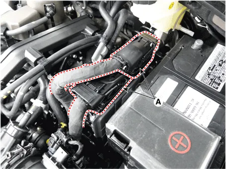
3.Disconnect the ECM connector (A).
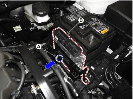
4.Release the fixing hook (A), and then removing the ECM (B).
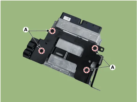
5.Remove the ECM after loosening the mounting bolts (A).
Tightening Torque :6.9 - 8.8 N.m (0.7 - 0.9 kgf.m, 5.1 - 6.5 lb-ft)
1.Install in the reverse order of removal.
2.If replaced the ECM, perform the reset and learning procedure using the diagnosis tool.(Refer to "Adjustment")

• Perform the following procedure when replacing ECM (New parts / Reused parts).
• ECM and TCM are integrated, TCM related procedures should be performed when the ECM is replaced.
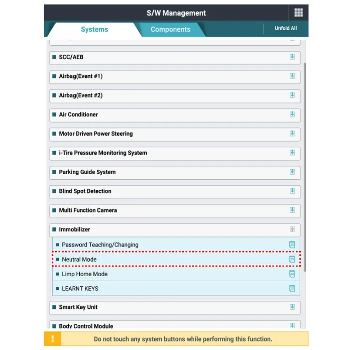
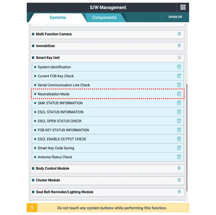
1.Perform the neutral mode using the diagnosis tool when replacing with a reused ECM.
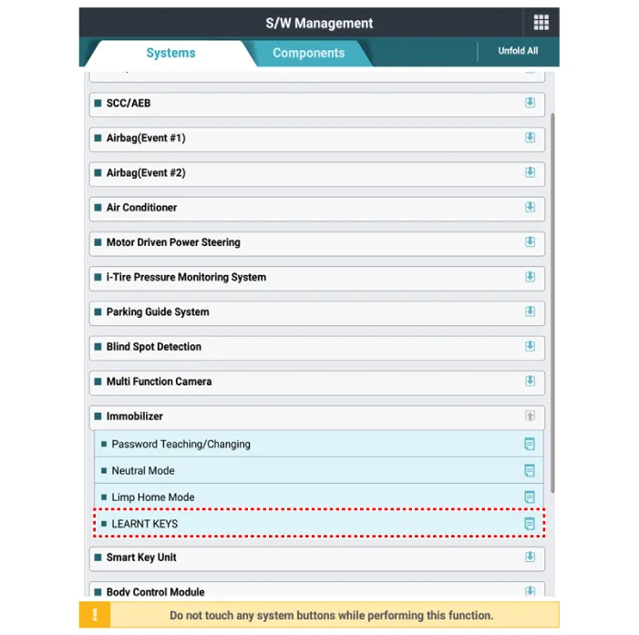
2.Perform the "Key Teaching" procedure by using the diagnosis tool.
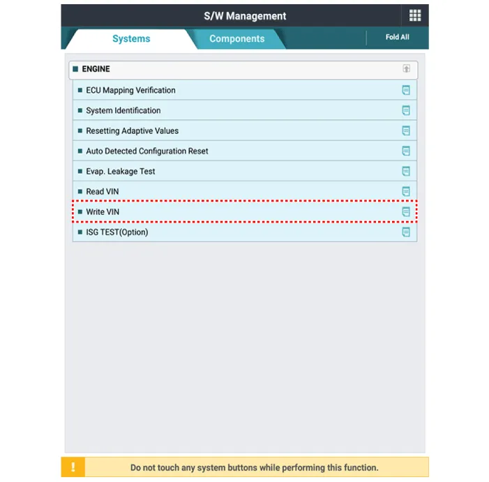
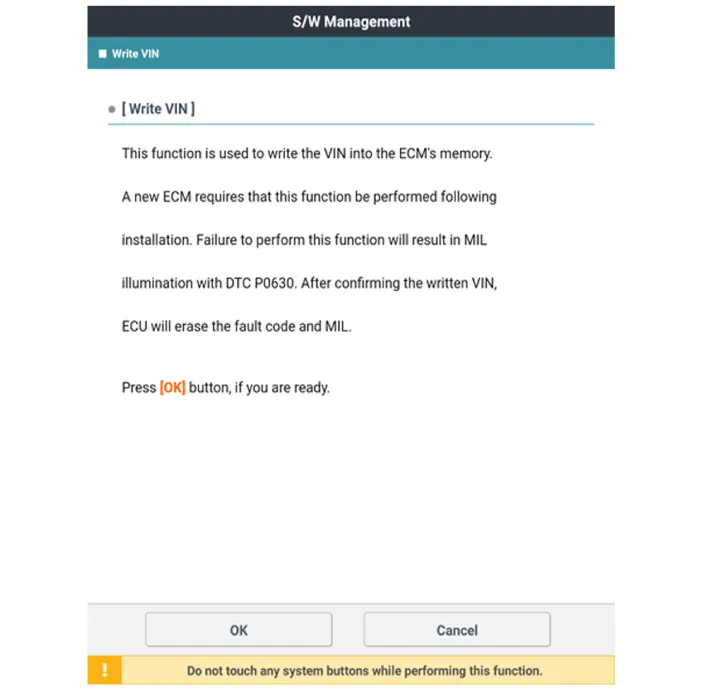
3.Perform the VIN writing procedure by using the diagnosis tool.
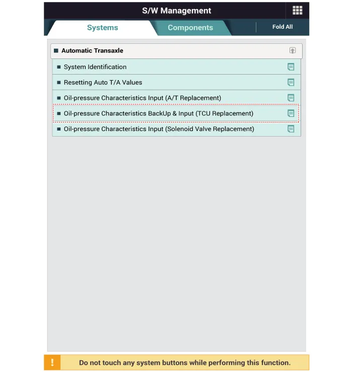
4.Perform the oil pressure characteristics backup procedure using the diagnosis tool.
5.Perform the ETC module learning procedure.(Refer to Engine Control / Fuel System - "ETC System")
6.Perform the TCM learning procedure.(Refer to Automatic Transaxle Control System - "Adjustment")
 Description and Operation
- OBD-II Review
1. Overview
The California Air Resources Board (CARB) began regulation of On Board
Diagnostics (OBD) for vehicles sold in California beginning with the
1988 model year. The fir ...
 Mass Air Flow Sensor (MAFS)
- Description
MAFS uses a hot-film type sensing element to measure the mass of intake
air entering the engine, and send the signal to ECM.A large amount of
intake air represents acceleration or ...
Other information:
Hyundai Tucson (NX4) 2022-2025 Service Manual: Rear Door Side Weatherstrip
- Replacement
[Rear door side weatherstrip]
1.Loosen the rear door checker (B) mounting bolt.Tightening torque :16.7 - 21.6 N.m (1.7 - 2.2 kgf.m, 12.3 - 15.9 lb-ft)
2.Detach the clips, then remove the rear door side weatherstrip (A).
3.To install, reverse removal procedure.
[Rear door bod ...
Hyundai Tucson (NX4) 2022-2025 Service Manual: Front Seat Shield Inner Cover
- Component Location
1. Front seat shield inner cover
- Replacement
• When removing with a flat-tip screwdriver or remover, wrap protective tape around the tools to prevent damage to components.
• Put on gloves to prevent hand injuries.
1.Remove the front ...
