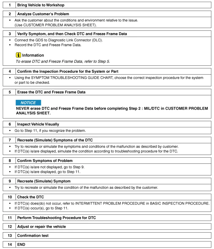
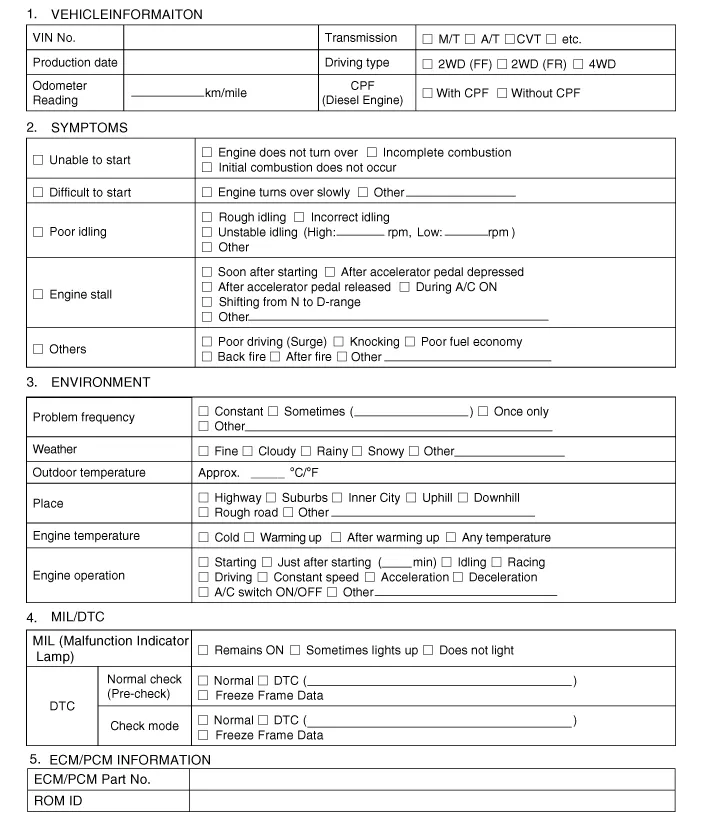
Hyundai Tucson: Engine Control / Fuel System / Troubleshooting

• The measured resistance in except for ambient temperature (20°C, 68°F) is reference value.
1.Clear Diagnostic Trouble Code (DTC).
2.Inspect connector connection, and check terminal for poor connections, loose wires, bent, broken or corroded pins, and then verify that the connectors are always securely fastened.
3.Slightly shake the connector and wiring harness vertically and horizontally.
4.Repair or replace the component that has a problem.
5.Verify that the problem has disappeared with the road test.
● SIMULATING VIBRATIONa.Sensors and Actuators: Slightly vibrate sensors, actuators or relays with finger.

• Strong vibration may break sensors, actuators or relays
b.Connectors and Harness: Lightly shake the connector and wiring harness vertically and then horizontally.
● SIMULATING HEATa.Heat components suspected of causing the malfunction with a hair dryer or other heat source.

• DO NOT heat components to the point where they may be damaged.
• DO NOT heat the ECM directly.
● SIMULATING WATER SPRINKLINGa.Sprinkle water onto vehicle to simulate a rainy day or a high humidity condition.

• DO NOT sprinkle water directly into the engine compartment or electronic components.
● SIMULATING ELECTRICAL LOADa.Turn on all electrical systems to simulate excessive electrical loads. (Radios, fans, lights, rear window defogger, etc.)
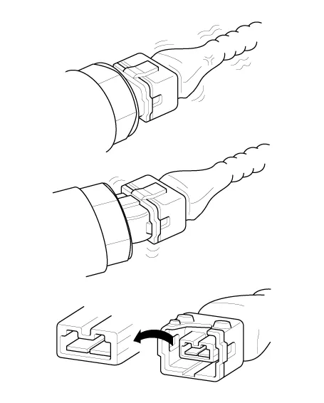
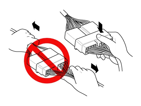
1.Handling of Connector
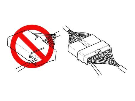
a.Never pull on the wiring harness when disconnecting connectors.
b.When removing the connector with a lock, press or pull locking lever.

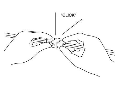
c.Listen for a click when locking connectors. This sound indicates that they are securely locked.
d.When a tester is used to check for continuity, or to measure voltage, always insert tester probe from wire harness side.
e.Check waterproof connector terminals from the connector side. Waterproof connectors cannot be accessed from harness side.
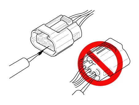

• Use a fine wire to prevent damage to the terminal.
• Do not damage the terminal when inserting the tester lead.
2.Checking Point for Connector
a.While the connector is connected:Hold the connector, check connecting condition and locking efficiency.
b.When the connector is disconnected:Check missed terminal, crimped terminal or broken core wire by slightly pulling the wire harness.Visually check for rust, contamination, deformation and bend.
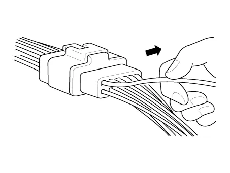
c.Check terminal tightening condition:Insert a spare male terminal into a female terminal, and then check terminal tightening conditions.
d.Pull lightly on individual wires to ensure that each wire is secured in the terminal.
3.Repair Method of Connector Terminal
a.Clean the contact points using air gun and/or shop rag.

• Never use sand paper when polishing the contact points, otherwise the contact point may be damaged.
b.In case of abnormal contact pressure, replace the female terminal.
1.Before removing the wire harness, check the wire harness position and crimping in order to restore it correctly.
2.Check whether the wire harness is twisted, pulled or loosened.
3.Check whether the temperature of the wire harness is abnormally high.
4.Check whether the wire harness is rotating, moving or vibrating against the sharp edge of a part.
5.Check the connection between the wire harness and any installed part.
6.If the covering of wire harness is damaged; secure, repair or replace the harness.
● Check Open Circuit
1.Procedures for Open Circuit
– Continuity Check
– Voltage Check
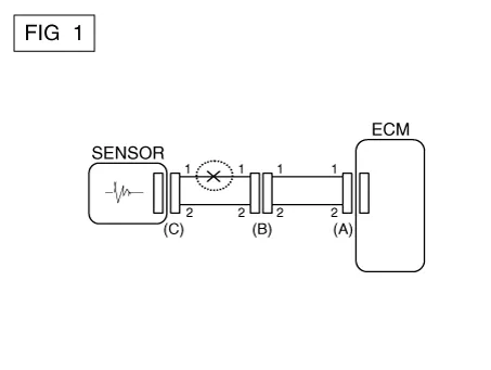
If an open circuit occurs (as seen in [FIG. 1]), it can be found by performing Step 2 (Continuity Check Method) or Step 3 (Voltage Check Method) as shown below.
2.Continuity Check Method

• When measuring for resistance, lightly shake the wire harness above and below or from side to side.
Specification (Resistance)1Ω or less → Normal Circuit1MΩ or Higher → Open Circuit
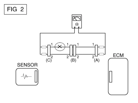
a.Disconnect connectors (A), (C) and measure resistance between connector (A) and (C) as shown in [FIG. 2].In [FIG.2.] the measured resistance of line 1 and 2 is higher than 1MΩ and below 1Ω respectively. Specifically the open circuit is line 1 (Line 2 is normal). To find exact break point, check sub line of line 1 as described in next step.
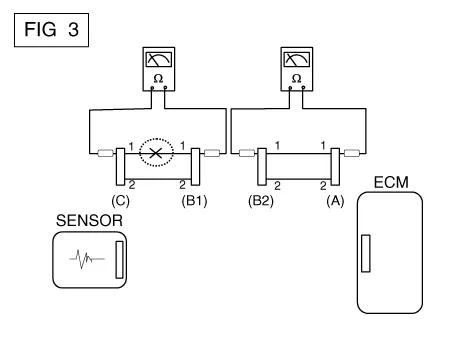
b.Disconnect connector (B), and measure for resistance between connector (C) and (B1) and between (B2) and (A) as shown in [FIG. 3].In this case the measured resistance between connector (C) and (B1) is higher than 1MΩ and the open circuit is between terminal 1 of connector (C) and terminal 1 of connector (B1).
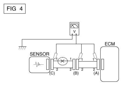
3.Voltage Check Method
a.With each connector still connected, measure the voltage between the chassis ground and terminal 1 of each connectors (A), (B) and (C) as shown in [FIG. 4].The measured voltage of each connector is 5V, 5V and 0V respectively. So the open circuit is between connector (C) and (B).
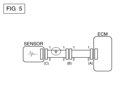
● Check Short Circuit
1.Test Method for Short to Ground Circuit
• Continuity Check with Chassis Ground
If short to ground circuit occurs as shown in [FIG. 5], the broken point can be found by performing Step 2 (Continuity Check Method with Chassis Ground) as shown below.
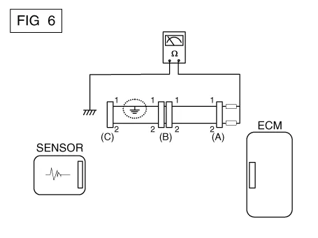
2.Continuity Check Method (with Chassis Ground)

• Lightly shake the wire harness above and below, or from side to side when measuring the resistance.
Specification (Resistance)1Ω or less → Short to Ground Circuit1MΩ or Higher → Normal Circuit
a.Disconnect connectors (A), (C) and measure for resistance between connector (A) and Chassis Ground as shown in [FIG. 6].The measured resistance of line 1 and 2 in this example is below 1Ω and higher than 1MΩ respectively. Specifically the short to ground circuit is line 1 (Line 2 is normal). To find exact broken point, check the sub line of line 1 as described in the following step.
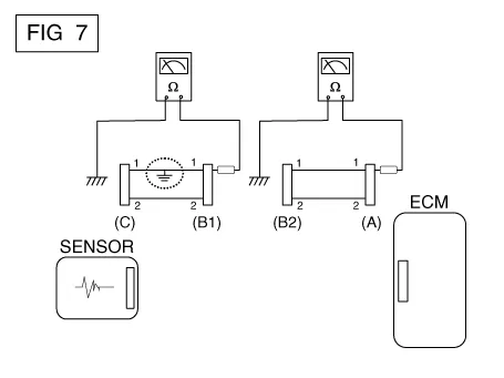
b.Disconnect connector (B), and measure the resistance between connector (A) and chassis ground, and between (B1) and chassis ground as shown in [FIG. 7].The measured resistance between connector (B1) and chassis ground is 1Ω or less. The short to ground circuit is between terminal 1 of connector (C) and terminal 1 of connector (B1).
| Main Symptom | Diagnostic Procedure | Also Check For | ||||||||||||||||||||||
| Unable to start (Engine does not turn over) |
| |||||||||||||||||||||||
| Unable to start (Incomplete combustion) |
|
| ||||||||||||||||||||||
| Difficult to start |
|
| ||||||||||||||||||||||
| Poor idling (Rough, unstable or incorrect Idle) |
|
| ||||||||||||||||||||||
| Engine stall |
|
| ||||||||||||||||||||||
| Poor driving (Surge) |
|
| ||||||||||||||||||||||
| Knocking |
|
| ||||||||||||||||||||||
| Poor fuel economy |
|
2)Check the fuel pressure
3)Check the injector
4)Test the exhaust system for a possible restriction
5)Check the ECT sensor and circuit
• DTC
• Low compression
• Intake air leaks
• Contaminated fuel
• Weak ignition spark
Hard to refuel
(Overflow during refueling)
1)Test the canister close valve
2)Inspect the fuel filler hose/pipe
• Pinched, kinked or blocked?
• Filler hose is torn
3)Inspect the fuel tank vapor vent hose between the EVAP. canister and air filter
4)Check the EVAP. canister
• Malfunctioning gas station filling nozzle (If this problem occurs at a specific gas station during refueling)
 Special Service Tools
- Special Service Tools
Tool (Number and name)IllustrationApplication
09353-24100Fuel Pressure Gauge
Measuring the fuel line pressure
0K353-D4100Fuel Pressure Gauge Adapter
Connection between the ...

Other information:
Hyundai Tucson (NX4) 2022-2025 Service Manual: Rear Occupant Alert Sensor
- Removal
1.Disconnect the negative (-) battery terminal.
2.Remove the cover (A) by using a flat-tip screwdriver.
3.Disconnect the connector (A) and then remove the occupant alert sensor.
- Installation
1.Install the occupant alert sensor.
2.Connect the negative (-) battery terminal. ...
Hyundai Tucson (NX4) 2022-2025 Service Manual: Front Seat Back Cover
- Component Location
1. Front seat back cover
- Replacement
• When removing with a flat-tip screwdriver or remover, wrap protective tape around the tools to prevent damage to components.
• Put on gloves to prevent hand injuries.
• Tak ...
