Hyundai Tucson: Starting System / Starter
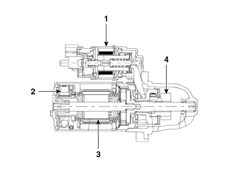
1. Solenoid
2. Brush assembly
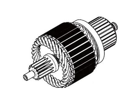
3. Armature
4. Overrun clutch
| Item | Specification | |
| Rated voltage | 12V, 1.2kW | |
| The number of pinion teeth | 11 | |
| Performance | Ampere | Max. 80 A |
| [No-load, 11.0V] | Speed | Min. 3,100 RPM |


• Be careful not to damage the parts located under the vehicle (floor under cover, canister, fuel tank) when raising the vehicle using the lift.(Refer to General Information - "Lift and Support Points")
1.Turn the ignition switch OFF and disconnect the battery (-) terminal.
2.Remove the engine room under cover.(Refer to Engine Mechanical System - "Engine Room Under Cover")
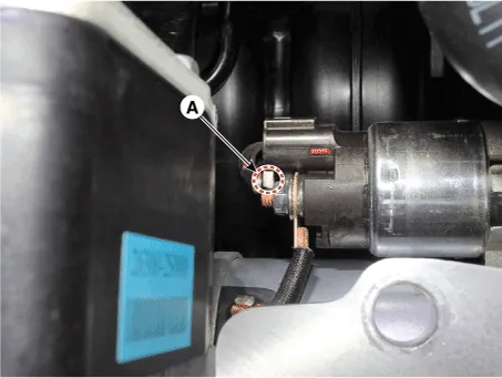
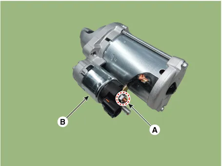
3.Disconnect the starter ST connector (A).

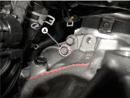
4.Remove the stater "B" terminal cable mounting nut (A).
Tightening torque :9.8 - 11.8 N.m (1.0 - 1.2 kgf.m, 7.2 - 8.7 Ib-ft)
5.Separate the clip (A) from the oil cooler pipe.
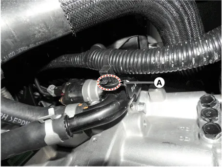
6.Remove the oil cooler pipe mounting bolt (A).
Tightening torque :18.6 - 23.5 N.m (1.9 - 2.4 kgf.m, 13.7 - 17.4 lb-ft)
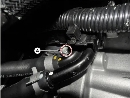
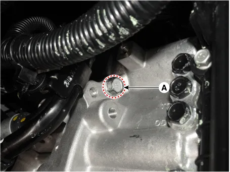
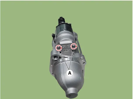
7.Remove the starter mounting bolt (A).
Tightening torque :49.0 - 63.7 N.m (5.0 - 6.5 kgf.m, 36.2 - 47.0 Ib-ft)
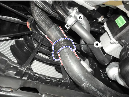
8.Separate the radiator hose (A) from the radiator hose bracket (B).
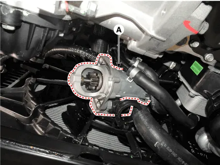
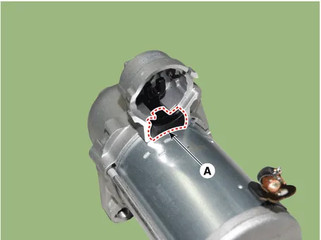
9.Remove the starter (A).
1.Install in the reverse order of removal.
1.Remove the M-terminal nut (A) on the magnetic switch assembly (B).
2.After loosening the screws (A), remove the magnetic switch assembly.
3.Remove the lever lest (A).
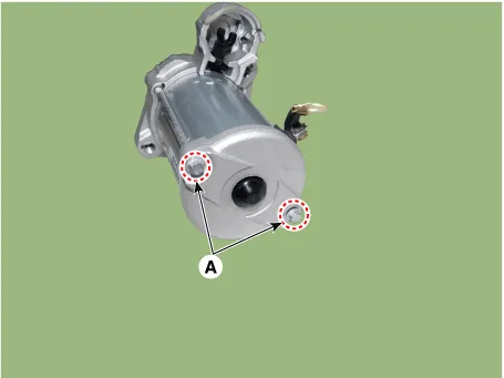
4.Remove the through bolts (A).
5.Separate the front bracket assembly from the planet gear shaft assembly and yoke assembly.
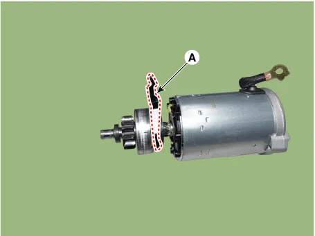
6.Remove the lever (A).
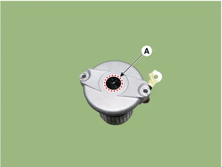
7.Remove the brush holder assembly cover cap (A).
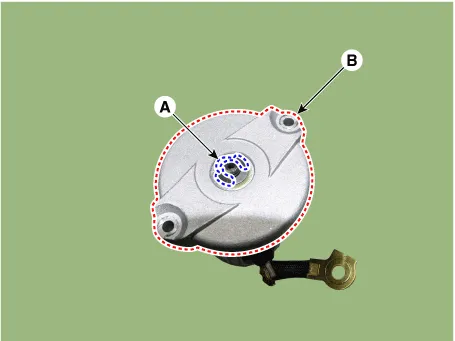
8.Remove the C-ring (A) and then remove the brush holder assembly cover (B).
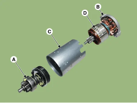
9.Detach the planet gear shaft assembly (A), brush holder assembly (B), armature assembly (D) and yoke assembly (C).
10.Press the stopper (A) using a socket (B).
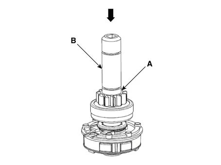
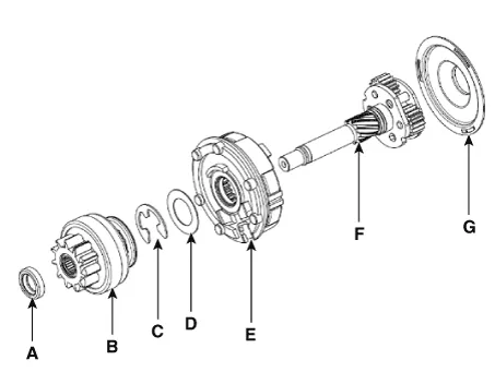
11.Remove the stopper (A), overrunning clutch (B), stopper (C), stopper washer (D), ring gear (E), drive shaft assembly (F), gasket seat (G).

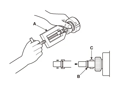
• Using a suitable pulling tool (A), pull the overrunning clutch stop ring (B) over the stopper (C).
1.Reassemble in the reverse order of disassembly.
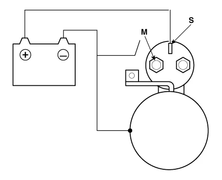
1.Disconnect the lead wire from the M-terminal of solenoid switch.
2.Connect the battery as shown. If the starter pinion pops out, it is working properly.

• To avoid damaging the starter, do not leave the battery connected for more than 10 seconds.
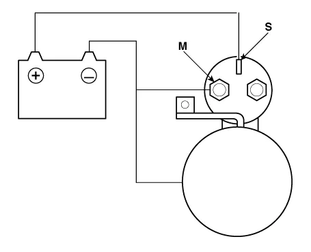
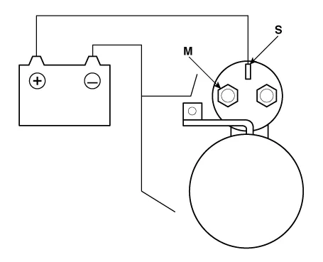
3.Disconnect the battery from the M terminal.If the pinion does not retract, the hold-in coil is working properly.

• To avoid damaging the starter, do not leave the battery connected for more than 10 seconds.
4.Disconnect the battery also from the body. If the pinion retracts immediately, it is working properly.

• To avoid damaging the starter, do not leave the battery connected for more than 10 seconds.
1.Place the starter motor in a vise equipped with soft jaws and connect a fully-charged 12-volt battery to starter motor as follows.
2.Connect a test ammeter (150-ampere scale) and carbon pile rheostats shown is the illustration.
3.Connect a voltmeter (15-volt scale) across starter motor.
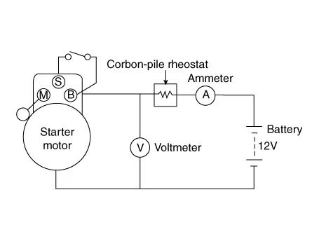
4.Rotate carbon pile to the off position.
5.Connect the battery cable from battery's negative post to the starter motor body.
6.Adjust until battery voltage shown on the voltmeter reads 11.5 and 11 volts.
7.Confirm that the maximum amperage is within the specifications and that the starter motor turns smoothly and freely.
| Items | Specification |
| Current (Max.) | Max. 80 A |
| Speed (Min.) | Min. 3,100 RPM |
1.Remove the starter.
2.Disassemble the starter as shown at the beginning of this procedure.
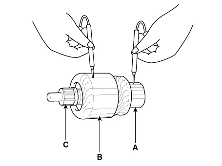
3.Inspect the armature for wear or damage from contact with the permanent magnet. If there is wear or damage, replace the armature.
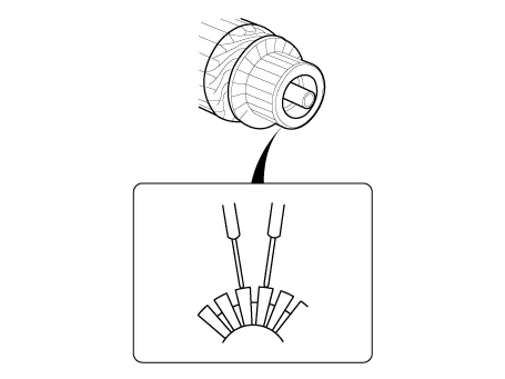
4.Check the commutator (A) surface. If the surface is dirty or burnt, resurface with emery cloth or a lathe within the following specifications, or recondition with #500 or #600 sandpaper (B).
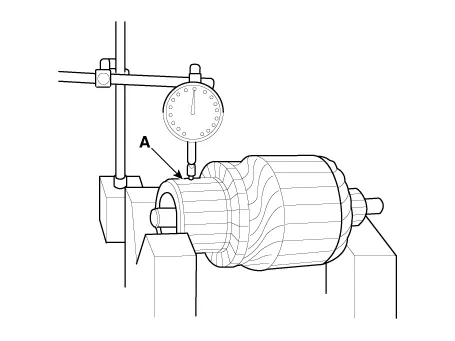
5.Measure the commutator (A) runout.
• If the commutator runout is within the service limit, check the commutator for carbon dust or brass chips between the segments.
• If the commutator run out is not within the service limit, replace the armature.
Commutator runoutStandard (New) : 0.05 mm (0.0019 in.) maxService limit : 0.08 mm (0.0031 in.)
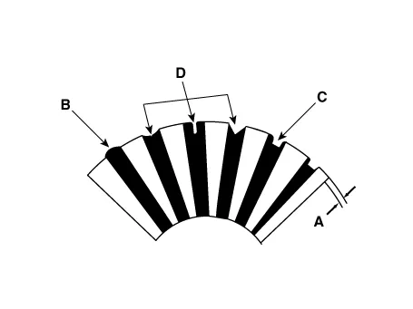
6.Check the mica depth (A). If the mica is too high (B), undercut the mica with a hacksaw blade to the proper depth. Cut away all the mica (C) between the commutator segments. The undercut should not be too shallow, too narrow, or v-shaped (D).
Commutator mica depthStandard (New) : 0.7 mm (0.0276 in.)Limit : 0.2 mm (0.0079 in.)
7.Check for continuity between the segments of the commutator. If an open circuit exists between any segments, replace the armature.
8.Check with an ohmmeter that no continuity exists between the commutator (A) and armature coil core (B), and between the commutator and armature shaft (C). If continuity exists, replace the armature.

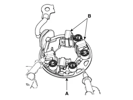
1.Check that there is no continuity between the (+) brush holder (A) and (-) plate (B). If there is continuity, replace the brush holder assembly.
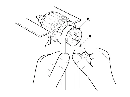
1.Slide the overrunning clutch along the shaft.Replace if it does not slide smoothly.
2.Rotate the overrunning clutch both ways.Does it lock in one direction and rotate smoothly in reverse? If it does not lock in either direction or locks in both directions, replace it.

3.If the starter drive gear is worn or damaged, replace the overrunning clutch assembly. (The gear is not available separately.)Check the condition of the flywheel or torque converter ring gear if the starter drive gear teeth are damaged.
1.Do not immerse parts in cleaning solvent.Immersing the yoke assembly and/or armature will damage the insulation wipe these parts with a cloth only.
2.Do not immerse the drive unit in cleaning solvent. The overrun clutch is pre-lubricated at the factory and solvent will wash lubrication from the clutch.
3.The drive unit may be cleaned with a brush moistened with cleaning solvent and wiped dry with a cloth.
 Troubleshooting
- Troubleshooting
• The battery must be in good condition and fully charged for this troubleshooting.
Trouble symptomProbable causeRemedy
Engine will not crankBattery c ...
 Starter Relay
- Inspection
1.Turn ignition switch OFF and disconnect the battery negative (-) terminal.
2.Remove the fuse box cover.
3.Remove the starter relay (A).
4.Check for continuity between the term ...
Other information:
Hyundai Tucson (NX4) 2022-2025 Service Manual: Air Cleaner
- Removal and installation
Air Cleaner Assembly
1.Disconnect the battery negative terminal.
2.Remove the engine cover.(Refer to Engine And Transaxle Assembly - “Engine Cover”)
3.Remove the air duct (A).
4.Remove the air cleaner assembly.(1)Disconnect the air flow sensor connector (A) ...
Hyundai Tucson (NX4) 2022-2025 Owner's Manual: Blind-Spot Collision Warning (BCW)
Blind-Spot Collision Warning uses
the rear corner radar to help detect
approaching vehicles in the driver’s blind
spot areas and warn you of a possible
collision with a warning message and
audible warning.
Blind-Spot Collision Warning helps
detect and warns you that a vehicle is in ...
