Hyundai Tucson: Surround View Monitor (SVM) / Repair procedures

• SVM calibration tool is required to perform tolerance calibration as shown below.
• Refer to the information below to purchase the SVM calibration tool.
– Tool Name : GDS SVM HYUNDAI (SVM-100)
– Representative purchase consultation email : sales@gitauto.com / purchase@gitauto.com
Tolerance calibration compensates for the error margins of surround view video that occur due to the installation tolerance when the four cameras that comprise the SVM system are installed.

• Tolerance calibration must be performed when the following actions are performed.
– When removing and installing a SVM camera.
– When conducting a body task such as the trunk task that causes the focus of the SVM camera to change.
– When replacing the outside rear view mirror with a SVM camera.
– When replacing the ADAS Parking ECU.
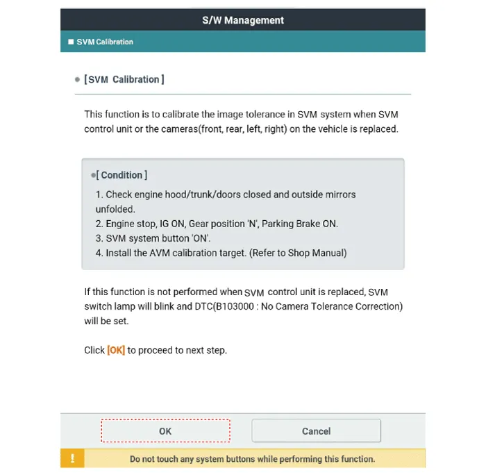
1.Prepare in advance as below.
– Confirm that the car hood, trunk and doors are closed.
– Close the door after getting in on the driver side.
– Engine running.
– Unfold both outside rear view mirrors.
– Shift the gear to N.
– Check the flashing state of LED indicator lamp in the SVM switch.
– During the advance preparation, do not install exhaust inhaler or other equipment that may block the view of rearview cameras.
– Also, as exhaust fume may block the rearview image, blow off the smoke by using a fan before performing tolerance calibration with engine running.
– Engage foot brake or electronic parking brake (EPB) to hold vehicle in place.
2.Before entering tolerance calibration mode, to check normal operation of SVM ECU and cameras, perform the following.
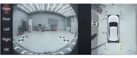
– Check that initial setting screen of SVM is displayed. (Front view image + surround view image when shifted to N)
– Check that front, rear, left and right images of surround view monitor are properly displayed.
– If images are properly displayed, enter tolerance calibration mode. Otherwise, if images are abnormally displayed or are not displayed, replace relevant part.
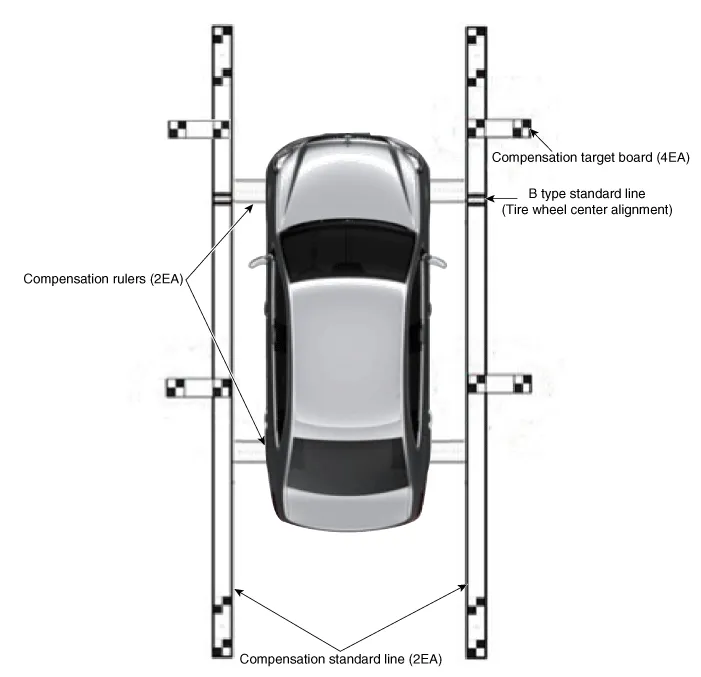
3.Install two calibration scales, two calibration reference line boards, and four calibration target boards around the vehicle by referring to the manual provided with the tools.

• There are two types (Type A & B) and the base line should be matched to vehicle type.
• Accurately set the location (distance/angle) of the center of white and black calibration board as this is the reference point.
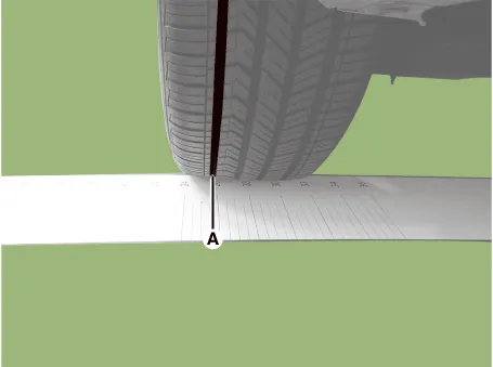
<A Type>(1)Align the vehicle in a straight line and install the SVM ruler on the front and rear tires in the direction of the arrow.

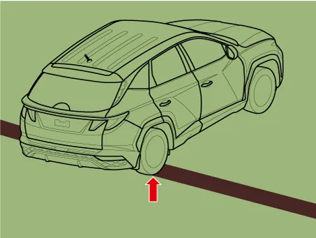
(2)The vehicle must be centered using the SVM rulers.

• Be careful not to crease when installing the SVM ruler.
• The measurements on both sides should be the same.
<Front>

• If a customer has replaced a tire of a different size from the other tires, SVM calibration may not be correct.
• The dimensions of the front and rear tires may be different.
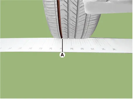
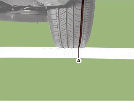
(3)The SVM reference line should be installed according to the end point of SVM ruler.

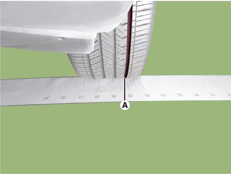
• Align the right-front wheel center of the tire with the base line on the SVM reference line.
• There are two types(Type A & B) and the Base line should be matched to vehicle type.
• Base line margin of error should be 3 cm (1.1 in.)
• Measure the margin of error at the end of the baseline.
<B Type>
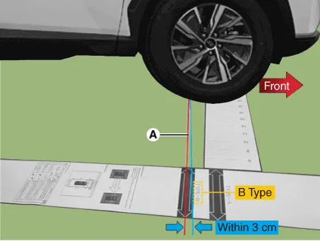

• Install it in the same way on the left hand side.
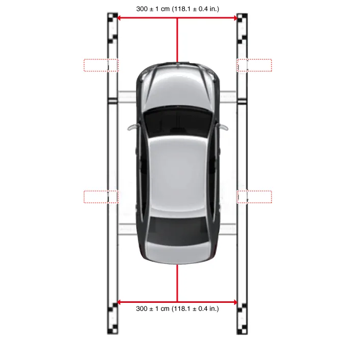
(4)After installation SVM rulers and SVM reference lines, measurement should be made to ensure that the left and right SVM reference line are installed parallel to each other.

• As shown in the figure below, the distance between the left and the right reference Line should be same.
• The allowance distance range from left line and right line is 300 ± 1 cm (118.1 ± 0.4 in.)
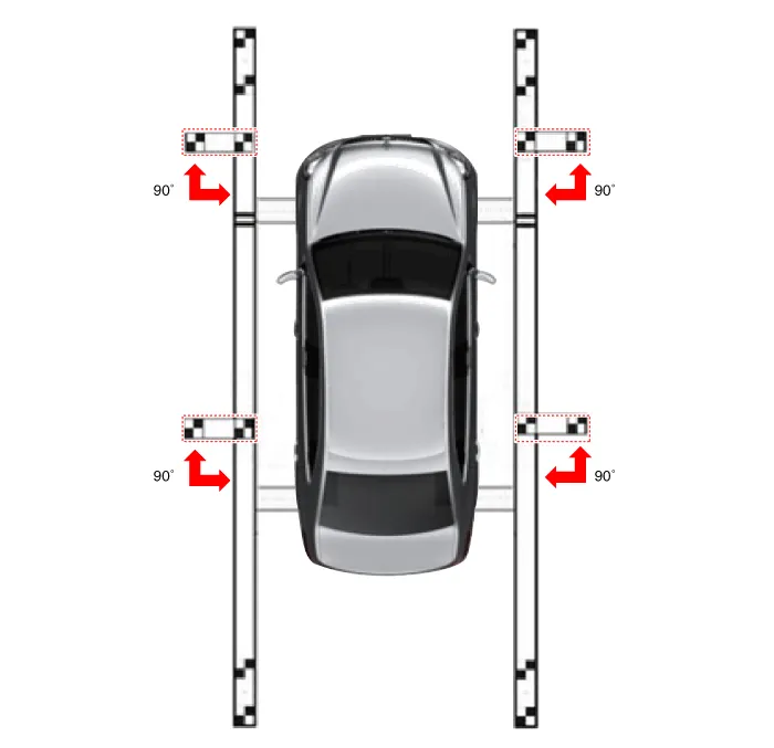
(5)Install the SVM target on the SVM reference line.

• Keep the SVM reference line and target angle at 90˚.
• Rotation error margin when aligning vehicle should be within 1° to left/right.
4.Maintain IG ON with vehicle stopped, check that the gear is in P, and engage parking brake even on flat ground.
5.Perform work with SVM switched "ON".
6.Connect the diagnostic tool to vehicle.
7.Select vehicle model and system.
8.Enter additional function in diagnostic tool.
9.Perform SVM manual tolerance calibration as shown on diagnostic tool.
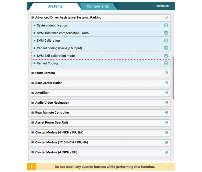

• When "SVM tolerance calibration - Manual" is clicked on the diagnostic tool screen, the SVM switch indicator lamp will flash.
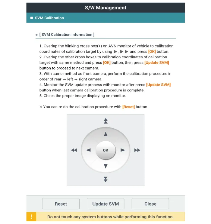
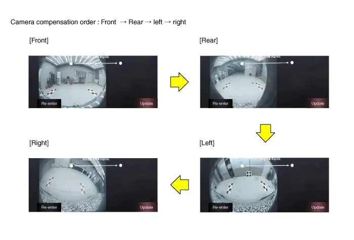
10.Click the [Front] button on the left tab of the H/UNIT to enter the area to be compensated.

• Before the compensation points are matched: "+" green light blinks
• When clicking the [OK] after compensation points are matched: "+" red light turns ON
• After matching the 4 front compensation points, click the [OK] button and then [Update SVM] button to move to the next camera compensation.
• Perform all compensation works in the order of front -> rear -> left -> right cameras.

11.After selecting the compensation points of all areas, click the [FINISH] button on the left tab of the H/UNIT monitor to finish the compensation work.
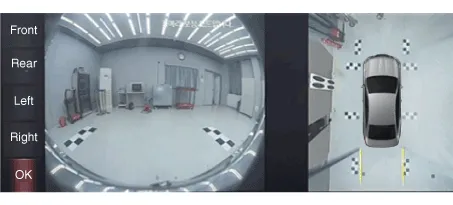
12.Click the parking view button to check whether the compensation is completed normally, and if the compensation was not performed normally, retry the manual tolerance compensation process.
 Troubleshooting
- Troubleshooting
1)After replacing controller, always check that the system operates properly.
2)If the failure persists after replacing the controller, do not replace the con ...
 Surround View Monitor (SVM) Unit
- Removal
1.Disconnect the negative (-) battery terminal.
2.Remove the crash pad center panel.(Refer to Body - "Crash Pad Center Panel")
3.Disconnect the SVM unit connector (A).
4.Loosen the ...
Other information:
Hyundai Tucson (NX4) 2022-2025 Service Manual: Repair procedures
- Variant Coding
When you need variant coding: – Replace Front View Camera with a new one
※ EOL Variant Coding and calibration required for new replacement
Front View Camera Variant Coding
Front view camera variant coding makes it possible to operate functions
for ea ...
Hyundai Tucson (NX4) 2022-2025 Service Manual: Special Service Tools
- Special Service Tools
Tool (Number and Name)IIIustrationUse
09568-1S100Ball joint remover
Removal of the tie rod end ball joint.
09568-4R100Lower arm ball joint remover
Removal of the lower arm ball joint.
...
