Hyundai Tucson: Rear Driveshaft Assembly / Rear Driveshaft
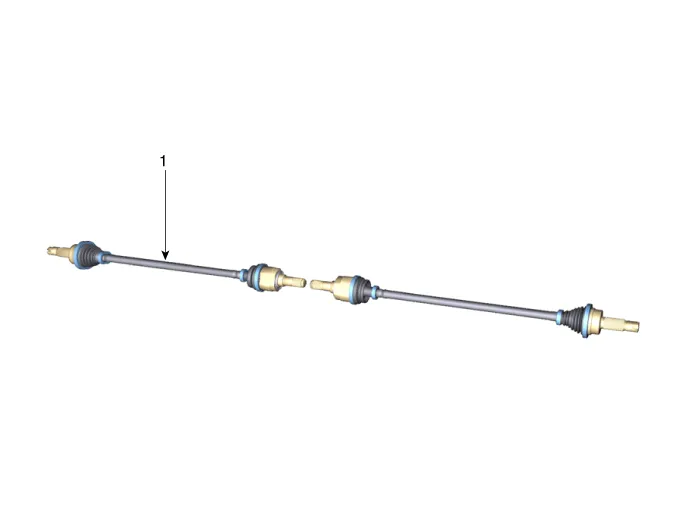
1. Rear drive shaft

• When lifting a vehicle using a lift, be careful not to damage the lower parts of the vehicle (floor under cover, fuel filter, fuel tank, canister).(Refer to General Information - "Lift and Support Points")
1.Loosen the rear wheel nuts slightly.Raise the vehicle, and make sure it is securely supported.
2.Remove the rear wheel and tire.(Refer to Suspension System - "Wheel")
3.Remove the rear brake caliper.(Refer to Brake System - "Rear Disc Brake")
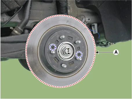
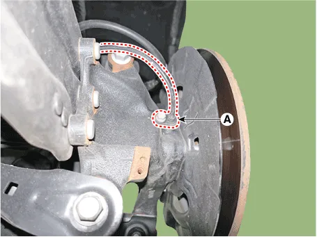
4.Remove the rear brake disc (A) after loosening the screw.
Tightening torque :4.9 - 5.9 N.m (0.5 - 0.6 kgf.m, 3.6 - 4.3 lb-ft)
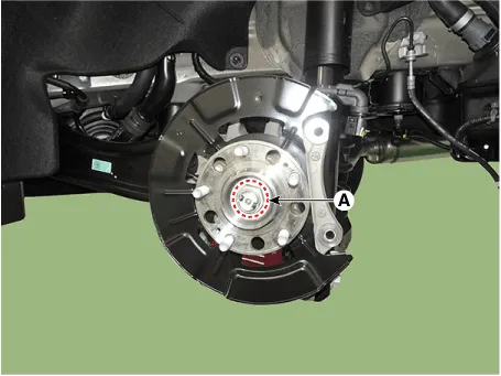
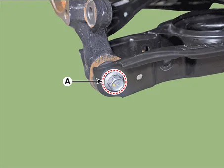
5.Loosen the caulking nut (A) from the rear hub.
Tightening torque : 294.2 - 313.8 N.m (30.0 - 32.0 kgf.m, 217.0 - 231.5 lb-ft)

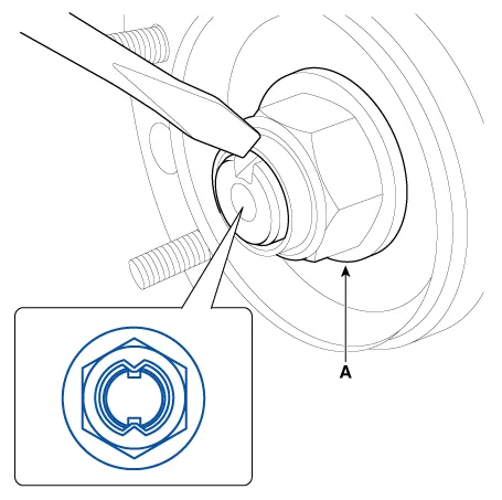
• The driveshaft lock nut (A) should be replaced with new ones.
• After installation driveshaft lock nut, stake the lock nut using a chisel and hammer as shown in the illustration below.
Caulking depth : 1.5 mm (0.591 in.)
6.Remove the rear hub assembly & dust cover (A) after loosening the mounting bolts.
Tightening torque: 98.0 - 117.6 N.m (10.0 - 12.0 kgf.m, 72.3 - 86.7 lb-ft)

7.Remove the rear wheel speed sensor (A) after loosening the mounting bolt.
Tightening torque :8.8 - 13.7 N.m (0.9 - 1.4 kgf.m, 6.5 - 10.1 lb-ft)
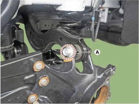
8.Remove the rear upper arm from the rear carrier after loosening the mounting bolt and nut (A).
Tightening torque :137.2 - 156.9 N.m (14.0 - 16.0 kgf.m, 101.2 - 115.7 lb-ft)
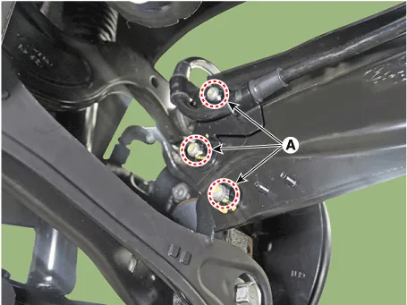
9.Remove the trailing arm after loosening the mounting nuts (A).
Tightening torque: 98.0 - 117.6 N.m (10.0 - 12.0 kgf.m, 72.3 - 86.7 lb-ft)
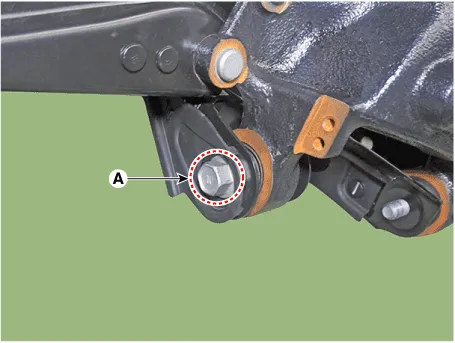
10.Remove the rear assist arm after loosening the mounting bolt and nut (A).
Tightening torque :156.9 - 176.5 N.m (16.0 - 18.0 kgf.m, 115.7 - 130.2 lb-ft)
11.Remove the rear lower arm after loosening the mounting bolt and nut (A).
Tightening torque :137.2 - 156.9 N.m (14.0 - 16.0 kgf.m, 101.2 - 115.7 lb-ft)
12.Remove the rear drive shaft (B) from the differential by using the pry bar (A).
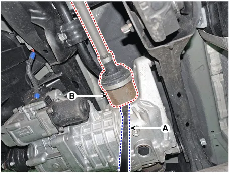
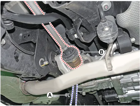

• Use a pry bar being careful not to damage the differential and joint.
• Do not insert the pry bar too deep, as this may cause damage to the oil seal.
• Do not pull the driveshaft by excessive force it may cause components inside the joint kit to dislodge resulting in a torn boot or a damaged bearing.
• Plug the hole of the differential case with the oil seal cap to prevent contamination.
• Support the driveshaft properly.
• Replace the retainer ring whenever the driveshaft is removed from the differential case.

• Do not disassemble the BJ assembly.
• Special grease must be applied to the driveshaft joint. Do not substitute with another type of grease.
• The boot band should be replaced with a new one.
1.Remove the TJ boot bands and pull the TJ boot from the TJ outer race.
(1)Using a pliers or flat-tipped (-) screwdriver, remove the LH boot band and LH TJ boot band from the driveshaft.
(2)Remove RH boot band and RH TJ boot band in the same way of LH removal procedure.

• Be careful not to damage the boot.
2.Pull out the driveshaft from the TJ outer race.
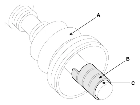
3.Remove the snap ring (A) and take out the inner race(B), cage(C) and balls(D) as an assembly.
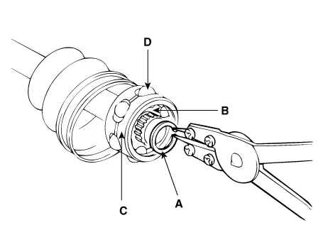
4.Clean the inner race, cage and balls without disassembling.
5.Remove the BJ boot bands and pull out the TJ boot and BJ boot.

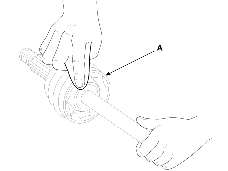
• If the boot (A) is to be reused, wrap tape(B) around the driveshaft splines(C) to protect the boot (A).
1.Wrap tape around the driveshaft splines (TJ side ) to prevent damage to the boots.
2.Apply grease to the driveshaft and install the boots.
3.Apply the specified grease to the inner race (A) and cage (B). Install the cage (B) so that it is offset on the race as shown.

• Use the grease included in the repair kit.
4.Apply the specified grease to the cage and fit the balls into the cage.
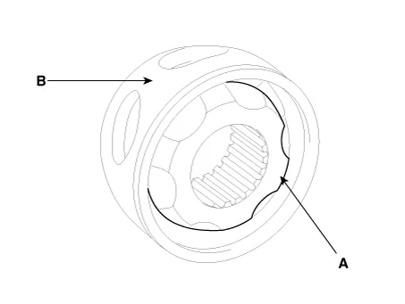
5.Position the chamfered side (A) as shown in the illustration. Install the inner race on the driveshaft(B), and then the snap ring.

6.Apply the specified grease to the outer race and install the BJ outer race onto the driveshaft.
7.Apply the specified grease into the TJ boot and install the boot with a clip.
8.Tighten the TJ boot bands.
9.Add the specified grease to the BJ as much as wiped away at inspection.
10.Install the boots.
11.Tighten the BJ boot bands.
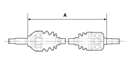
12.To control the air in the TJ boot, keep the specified distance between the boot bands when they are tightened.
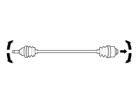
1.Check the driveshaft boots for damage and deterioration.
2.Check the ball joint for wear and damage.
3.Check the splines for wear and damage.
4.Check the driveshaft for cracks and wears.
5.Check the TJ outer race, inner race, cage and balls for rust or damage.
6.Check for water, foreign matter, or rust in the BJ boot.

• When the BJ assembly (A) is to be reused, do not wipe away the grease.
• Check that there are no foreign substances in the grease. If necessary, clean the BJ assembly (A) and replace grease.
1.To install, reverse the removal procedures.
2.Check the alignment.(Refer to Suspension System - "Alingment")


Other information:
Hyundai Tucson (NX4) 2022-2025 Service Manual: Crankcase Check Valve
- Removal and Installation
• Be careful not to damage the parts located under the vehicle
(floor under cover, canister, fuel tank) when raising the vehicle using
the lift.(Refer to General Information - "Lift and Support Points")
1.Disconnect the battery (-) terminal.
...
Hyundai Tucson (NX4) 2022-2025 Owner's Manual: Slide Open/Close
Push the sunroof switch rearward.
The sunroof glass slides open. If the
power sunshade is closed, the power
sunshade opens first and then the
sunroof glass opens.
Push the sunroof switch forward. The
sunroof glass closes.
Push the sunroof switch forward or
rearward to th ...
