Hyundai Tucson: Parking Distance Warning (PDW) / Description and Operation
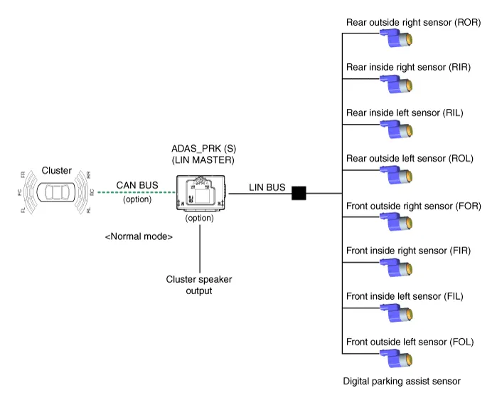
• PDW consists of 8 sensors (front : 4 units, rear : 4 units) that are used to detect obstacles and transmit the result in three separate warning levels, the first, second and third to IBU via LIN communication.
• IBU decides the alarm level by the transmitted communication message from the slave sensors, then operates the buzzer or transmits the data for display.
Initial mode
1.System initializing time
– PDW-F : 500ms after IGN1+ initial D Gear + below 10 Km/h
– PDW-R : 500ms after IGN1+ initial R Gear
2.PDW recognizes LID and sets the sensor ID up during initialization.
3.PDW activates each sensor and then executes the diagnosis after finishing initialization of IPM(IBU).
4.PDW starting buzzer is normally worked, when sensor does not send an error message and after finishing error diagnosis.
5.If any failure is received from the any sensors, PDW starting buzzer does not work but the failure alarm is operated for a moment.If you have display option, warning sign is also shown on it.

6.IBU memorizes the completed initializing status of sensor.
Normal mode
1.PDW-F : Lin communication starts and keeps the routine after IGN1 ON+D gear + below 10 km/h. PDW-R : Lin communication starts and keeps the routine after IGN1 ON+R gear
2.After initializing, the routine starts at once without PDW starting warning sound.
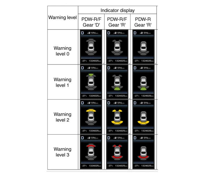
3.Alarms of obstacle consists of 3 level 1,2,3 step and 1,2 alarm sounds intermittently and 3 alarm sounds continuously. 1 level alarm doesn't exist in the front ultrasonic sensor.
4.In display, the data of each sensor is sent from IBU to display, for example cluster. CAN communication is used for transmission and maximum gateway time is 50ms.
5.The efficient vehicle speed of PDW operation is under 10Km/h.
6.Operation doesn't start or stops at gear N, P.
| Level | Distance range | Allowed range |
| 1 | Front : 61 - 100 cm (24.02 - 39.37 in.) / Rear : 61 - 120 cm (24.02 - 47.2 in.) | ± 15 cm (5.90 in.) |
| 2 | 31 - 60 cm (12.20 - 23.62 in.) | ± 15 cm (5.90 in.) |
| 3 | 0 - 30 cm (0 - 11.81 in) | ± 10 cm (3.94 in.) |
*Measurement condition : PVC pipe - Diameter 75 mm (0.0394 in.), length 1 m (39.37 in.), at normal temperature

 Components and Components Location
- Component Location
1. ADAS_PRK (S)2. Ultrasonic Sensor
※ PDW function is applied alone, it is integrated into ADAS_PRK (S) ...
Other information:
Hyundai Tucson (NX4) 2022-2025 Service Manual: Special Service Tools
- Special Service Tools
Tool(Number and Name)Illustration Use
Ball joint remover09568-1S100
Removal of the tie rod end ball joint.
Lower arm ball joint remover09568-4R100
Removal of the lower arm ball joint.
Band installer0K495-C5000
Used for installing ear type boot band
Band installer0949 ...
Hyundai Tucson (NX4) 2022-2025 Service Manual: Fuel Pump Motor
- Removal
1.Remove the fuel pump.(Refer to Fuel Delivery System - "Fuel Pump")
2.Disconnect the fuel sender connector (A).
3.Release the fixing hook (A) and then remove fuel sender (B) in the arrow direction.
4.Disconnect the fuel pump motor connector (A).
5.Remove the fixing pin (A) ...
