Hyundai Tucson: Power Liftgate Module / Description and Operation
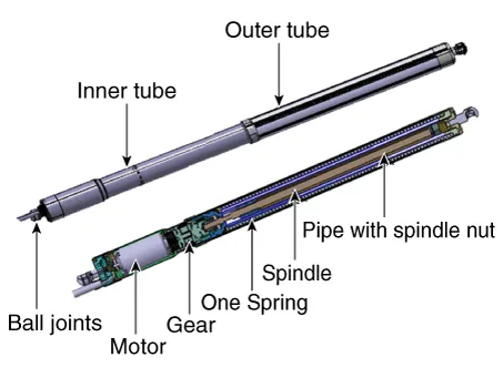
1.PTG Unit
2.PTG Latch Assembly
3.PTG Spindle
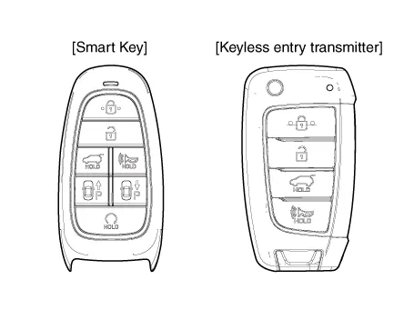
4.SMK (Smart key)
5.Liftgate inner switch
6.Liftgate buzzer
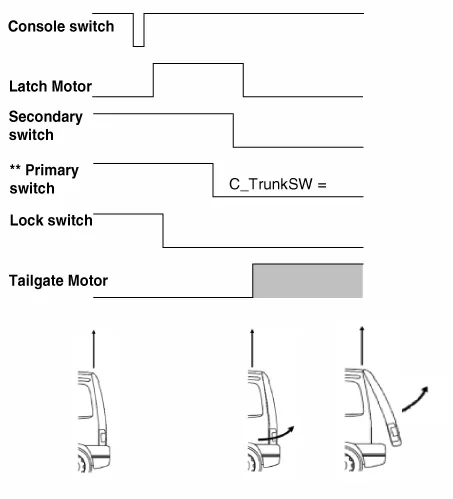
1.Opening can be triggered after a signal is received from, driver-console switch, outside handle switch, remote Key (FOB)
2.The latch will be released (by SJB) by actuation of latch motor.
3.On latch release, the liftgate latch pops out of the striker.
4.PTG module controls the liftgate motor in order to open the liftgate.
5.The rotating speed of the liftgate motor can be hall sensor that is built in the motor.
6.Opening angle of the liftgate is calculated by counting the input pulse signals from Hall sensor.

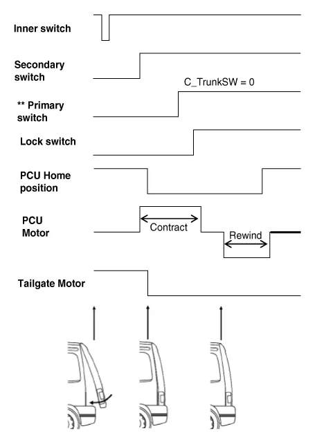
1.Closing can be triggered after receiving a signal from, console (driver) switch, ouside handle switch, remote key (FOB), inner switch
2.PTG module controls the liftgate motor in order to close the liftgate
3.Closing angle of the liftgate is calculated by counting the input pulse signlas from hall sensor
4.The rotating speed of the liftgate motor can be hall sensor that is built in the motor
5.The liftgate latch engages with the striker and the latch is locked mechanically (Latch unlock → Latch lock)
6.PTGM stops the liftgate motor operation after detecting the liftgate latch's secondary signal
7.On detecting the latch's secondary signal, the power close unit (PCU) starts the contract (cinch) operation and stops after the latch lock signal is detected
8.After contract operation is stopped, PCU is rewound until the PCU home position is reached
9.The liftgate is completely closed and latch is fully locked

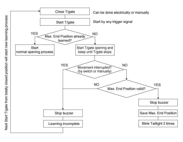
1.Maximum Point for OpeningAbove this position a start in opening direction could make the liftgate move beyond the Maximum Basic Position and overload the mechanical system (hinges).Therefore the start of an opening action above this point is disabled.Anyway the liftgate moves beyond this point, if it has been started at a lower position.
2.Learned Mechanical End PositionThis is the mechanical block position while opening and is considered to be 100% opening. During the first liftgate opening this position is learned.After learning, the liftgate will not move beyond the Maximum Basic Position, which is defined by the Learned Mechanical Position – Security Distance.All positions are defined by parameters in the ECU or programmed by the user (Basic Programmed Position)
1.The customizable Programmed Basic Position is set equal to the Maximum Basic Position after the Learned Mechanical End Position is learned.
– The customer can change the Programmed Basic Position to any new position between the Maximum Point For Closing and the Maximum Basic Position.
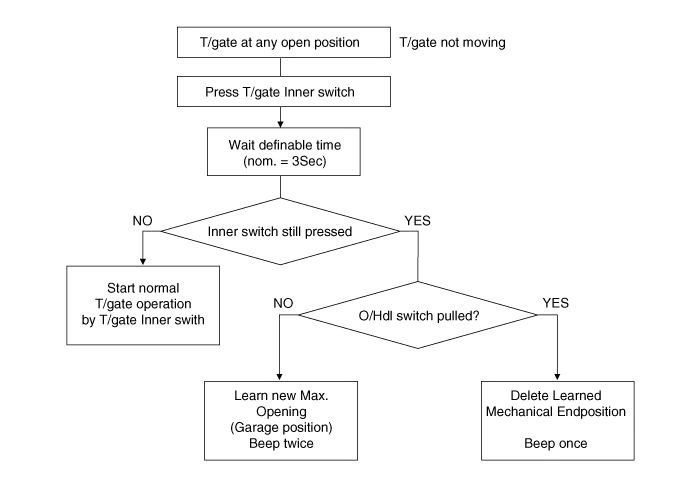
– If the customer wants to set a new Programmed Basic Position below the actual Programmed Basic Position, he has to move the liftgate electrically or manually to the new position and has to push the Inner Switch for e.g. 3 seconds (time can be modified by parameter)
– If the customer wants to set a new Programmed Basic Position above the actual Programmed Basic Position he has to move the liftgate manually to the new position and has to push the Inner Switch for 5 seconds (time can be modified by parameter)
– If the user tries to program a liftgate position above the Maximum Basic Position, the ECU will set the Programmed Basic Position to the Maximum Basic Position.
| BUZZER | LAMP *) | Remark | |
| T/gate start | 2 times | 2 times | When T/gate is triggered by Remote Contol or T/gate Console Switch |
| T/gate start | n.a. | n.a. | When T/gate is triggered by T/gate Inner Switch or T/gate Outer Handle Switch |
| T/gate stop | n.a. | n.a. | |
| System error | 3 Times | - | PCU/ Liftgate antiplay active, 0ver-/undervoltage condition, Endposition-/position error, spindle error, CAN error, Latch closed when Liftgate open |
| T/gate not closed | 10 times | 10 times | Latch Lock Switch not present |
| During Calibration run | Continuous ON-OFF beeping | n.a. | Activate buzzer but not C_PTHazard |
| Max. End Position learned | n.a. | 2 times | Buzzer confirms learning finished |
| Max. End Position deleted | 1 time | n.a. | Buzzer confirms "position deleted" |
| Car is moving with open T/gate | 10 times | n.a. | T/gate open AND Speed >3km/h |
| Garage Position saved | 2 times | n.a. | Buzzer confirms "New Garage Position" |
*) Lamp will be synchronized by sending C_PTHazard simultaneously to Buzzer signal

 Components and Components Location
- Component Location
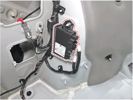
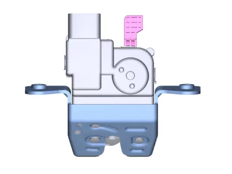
1. Buzzer2. Liftgate open switch (Crsah pad lower switch)3. Fob key4. Spindle Drive (2EA)5. Liftgate inner switch6. Power Latch7. PTG Control Module
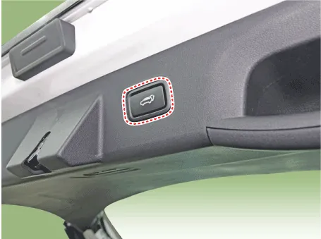
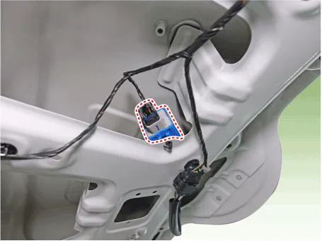
Liftgate Inner Switch
...
Other information:
Hyundai Tucson (NX4) 2022-2025 Service Manual: Delivery Pipe
- Removal
Low Pressure Delivery Pipe
1.Release the residual pressure in fuel line.(Refer to Fuel Delivery System - "Release Residual Pressure in Fuel Line")
2.Turn the ignition switch OFF and disconnect the battery negative (-) cable.
3.Disconnect the injector connector (A).
4.Disconnec t ...
Hyundai Tucson (NX4) 2022-2025 Service Manual: Components and Components Location
- Components
1. Steering column2. Lighting swtich3. Wiper switch4. Clock spring5. Steering wheel6. Driver airbag (DAB)
...
