Hyundai Tucson: Air Conditioning System / Compressor
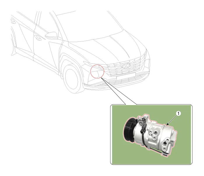
1. Compressor
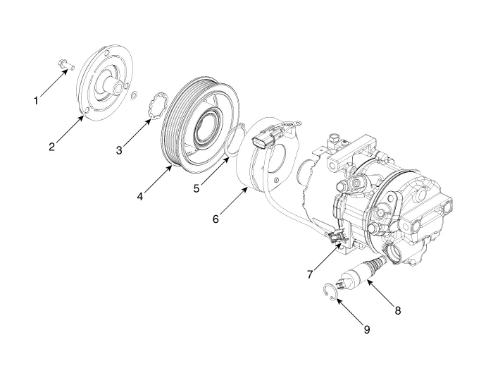
1. Clutch bolt
2. Disc & Hub assembly
3. Snap ring (Rotor)
4. Pulley
5. Snap Ring (Stator)
6. Clutch spacer
7. Compressor
8. Electric Control Valve (ECV)
9. Electric Control Valve (ECV) snap ring
1.If a compressor is available, the air conditioner is operated for a few minutes in the engine idle state and then the engine is stopped.
2.Disconnect the negative (-) battery terminal.
3.Recover the refrigerant with a recovery/charging station.(Refer to Air conditioning System - "Repair procedures")
4.Remove the engine room under cover.(Refer to Engine Mechanical System - "Engine Room Under Cover")
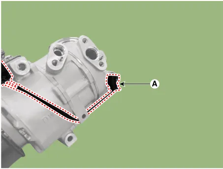
5.Loosen the mounting nuts and separate the suction line (A), discharge line (B).
Tightening torque : 21.6 - 32.4 N.m (2.2 - 3.3 kgf.m, 15.9 - 23.9 lb-ft)

• Plug or cap the lines immediately after disconnecting them to avoid moisture and dust contamination.
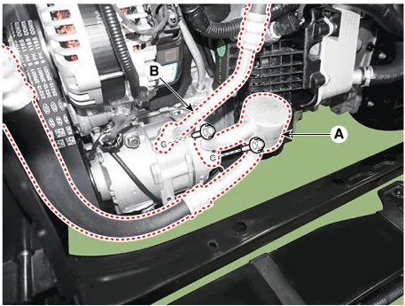
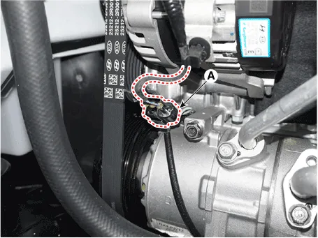
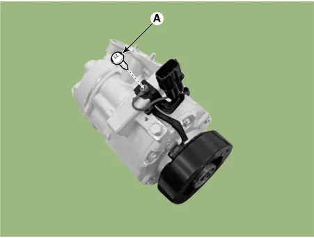
6.Press the lock pin and separate the ECV connector (A).
7.Loosen the drive belt.(Refer to Engine Mechanical System - "Drive Belt")
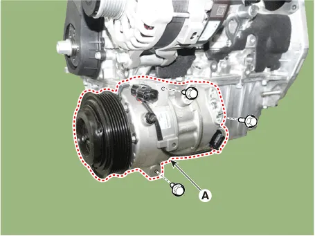
8.Loosen the mounting bolts and remove the compressor assembly (A).
Tightening torque : 20.0 - 33.0 N.m (2.04 - 3.36 kgf.m, 14.8 - 24.3 lb-ft)
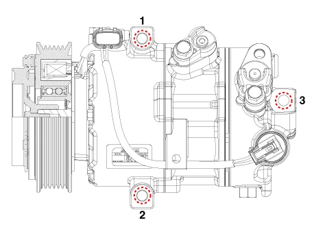
1.Make sure that the compressor (A) mounting bolt of the correct length is screwed in. Tighten the mounting bolts in the specified tightening order.
2.Install in the reverse order of removal.
– If you install a new compressor, drain all the refrigerant oil from the removed compressor and measure its volume. Subtract the volume of drained oil from the original capacity. The result is the amount of oilcompressor oil you should drain from the new compressor (through the suction fitting).
– Replace the O-rings with new ones at each fitting, and apply a thin coat of refrigerant oil before installing them. Be sure to use the right O-rings for R-134a, R-1234yf to avoid leakage.
– To avoid contamination, do not return the oil to the container once dispensed, and never mix it with other refrigerant oils.
– Immediately after using the oil, replace the cap on the container and seal it to avoid moisture absorption.
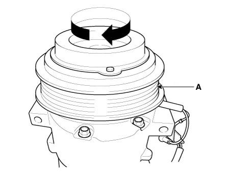
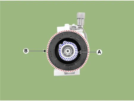
1.Check the pulley (A) bearing play and drag by rotating the pulley by hand. Replace the pulley with a new one if it is noisy or has excessive play/drag.
External Control Valve Compressor Inspection (GDS)
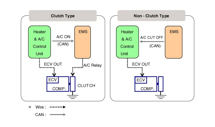
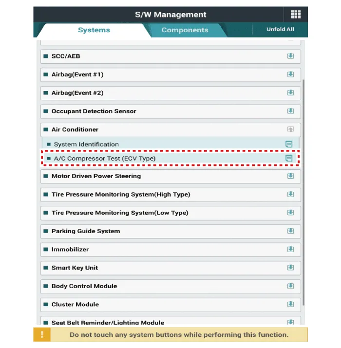
Compressor type: Fixed type compressor, External control valve, Internal control valve.In cases of fixed type and internal control valve, it is possible to inspect compressor's operation with clutch noise. When it comes to External control valve, however, it cannot be checked in this way bacause it doesn't have a clutch. So, ECV should be inspected with GDS as below.1.Connect GDS to the vehicle and select 'Aircon Compressor Test(ECV type)' [ECV1]
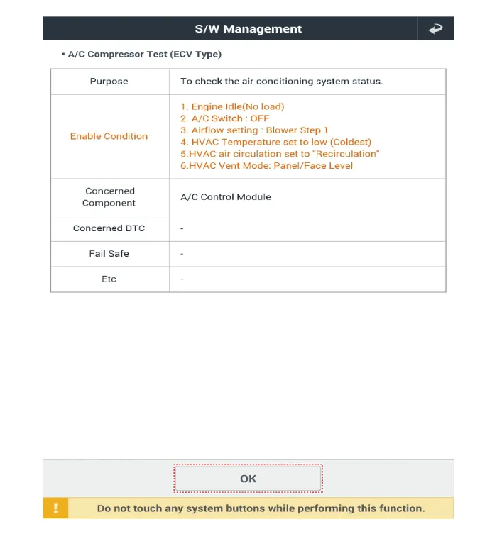
2.Make the vehicle ready as the GDS instruction on the monitor. (Turn off A/C 'switch' only)
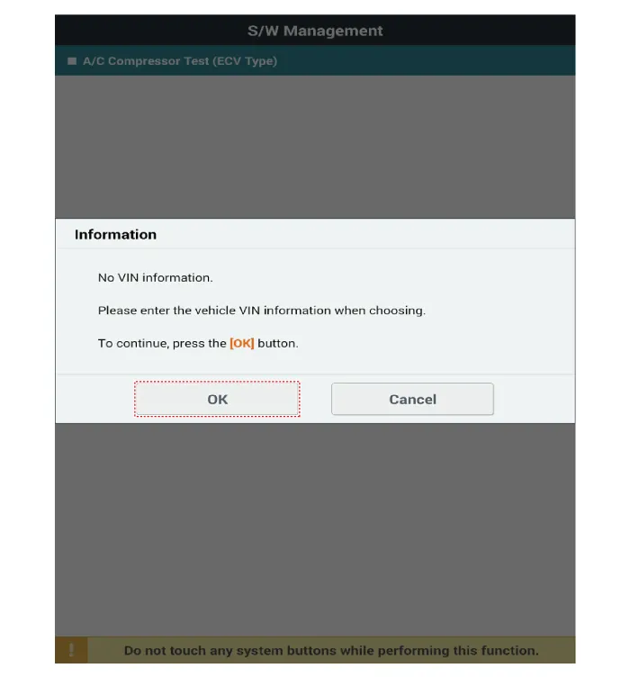
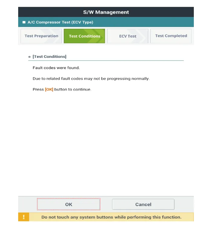
3.Check if other DTC codes are found before inspect ECV compressor. If so, solve that problems first. If not, press 'OK' button to continue.

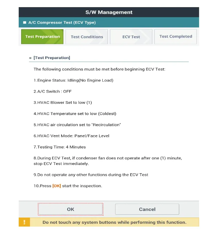
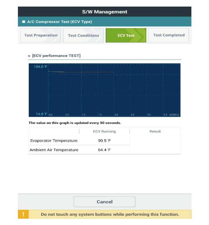
4.Start inspection


5.Check the result of inspection.[ECV7]
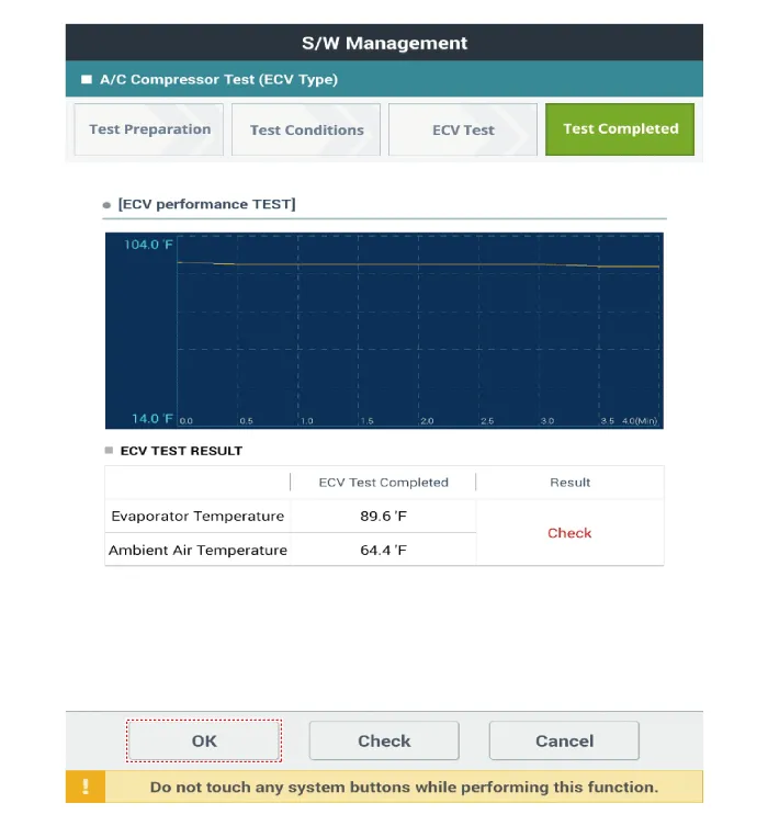
6.If the result shows "Check" , click "Check" and follow the instruction.
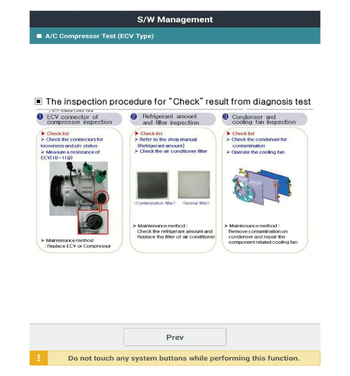
7.Inspect ECV again from the first step.
1.Remove the compressor.(Refer to Air Conditioning System - "Compressor")
2.Remove the clutch bolt (A) while holding the pulley with a clutch bolt remover (09977-3R000).
Tightening torque :15.0 - 21.0 N.m (1.53 - 2.14 kgf.m, 11.1 - 15.5 lb-ft)
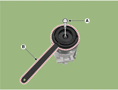
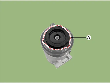
3.Remove the Disc & Hub assembly (A).
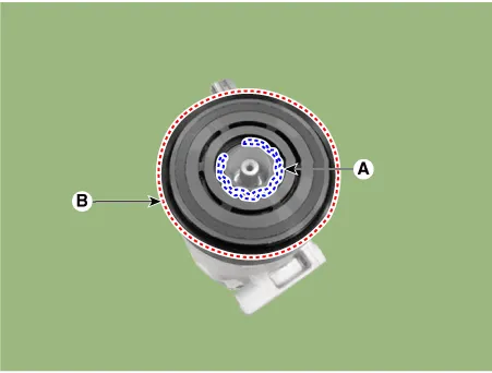
4.Remove the pulley (B) after removing the snap ring (A) with a snap ring plier.
5.Disconnect the ECV connector (A).
6.Remove the stator ground screw (A).
7.Remove the stator assembly (B) after removing the snap ring (A) by using snap ring pliers.
1.Reassemble in the reverse order of disassembly.

• Wipe the moving surfaces of the pulley and compressor with a volatile solvent.
• Make sure that the snap ring is fully seated in the groove after assembling the snap ring.
• Make sure that the pulley rotates smoothly after assembling the pulley.
 Refrigerant Line
- Components
1. Suction & Liquid Pipe Assembly
- Replacement
1.If a compressor is available, the air conditioner is operated for a
few minutes in the engine idle state and then the ...
 Condenser
- Components Location
1. Condensor
- Inspection
1.Check the condenser fins for clogging and damage. If clogged,
clean them with water, and blow them with compressed air. If bent,
gent ...
Other information:
Hyundai Tucson (NX4) 2022-2025 Service Manual: Canister
- Removal
• Be careful not to damage the parts located under the vehicle
(floor under cover, canister, fuel tank) when raising the vehicle using
the lift.(Refer to General Information - "Lift and Support Points")
1.Turn the ignition switch OFF and disconnect the batter ...
Hyundai Tucson (NX4) 2022-2025 Owner's Manual: Airbag inflation conditions
Front airbags
Airbag inflation conditions
Front airbags are designed to inflate
in a frontal collision depending on the
severity of impact.
Side and curtain airbags
Side and curtain airbags are designed
to inflate when an impact is detected by
side collision sensors depending on th ...
