Hyundai Tucson: Blower / Blower Unit

1. Blower unit assembly
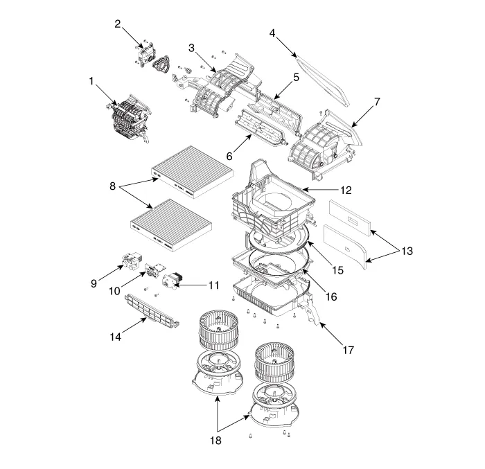
1. Blower unit assembly
2. Intake actuator
3. Intake duct case [LH]
4. Intake seal
5. Intake door(1)
6. Intake door(2)
7. Intake duct case [RH]
8. Climate control actuator
9. PWM blower module
10. Blower resistor
11. Power mosfet
12. Blower upper case
13. Blower NVH pad
14. Air filter cover
15. Blower blind case
16. Blower lower case
17. Blower cover
18. Blower motor assembly
1.Disconnect the negative (-) battery terminal.
2.Recover the refrigerant with a recovery/recycling/charging station.(Refer to Air conditioning System - "Repari procedures")
3.When the engine is cool, drain the engine coolant from the radiator.(Refer to Engine Mechanical System - "Coolant")
4.Remove the cowl top cover.(Refer to Body (Interior and Exterior) - "Cowl Top Cover")
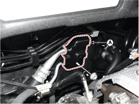
5.Loosen the mounting nut and separate the expension valve cover (A).
Tightening torque : 7.8 - 11.8 N.m (0.8 - 1.2 kgf.m, 5.8 - 8.7 lb-ft)
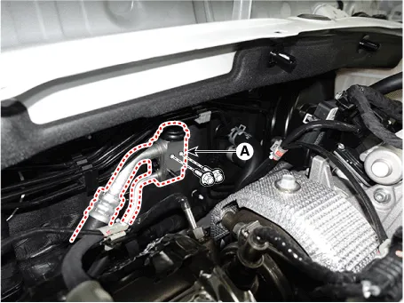
6.Loosen the mounting bolts and separate the expension valve (A) from the evaporator core.
Tightening torque :21.6 - 32.4 N.m (2.2 - 3.3 kgf.m, 15.9 - 23.9 lb-ft)
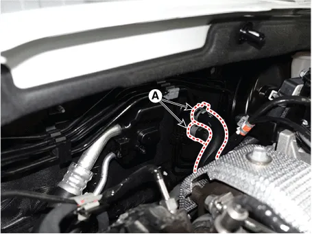
7.Separate the heater hose (A).
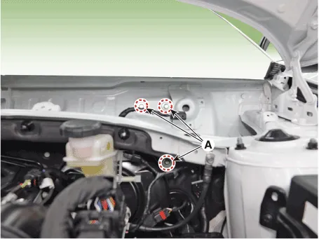
8.Loosen the cowl cross bar assembly mounting bolts (A).
Tightening torque : 16.7 - 25.5 N.m (1.7 - 2.6 kgf.m, 12.3 - 18.8 lb-ft)
9.Remove the front seat assembly.(Refer to Body (Interior and Exterior) - "Front Seat Assembly")
10.Remove the floor console assembly.(Refer to Body (Interior and Exterior) - "Floor Console Assembly")
11.Remove the front pillar trim.(Refer to Body (Interior and Exterior) - "Front Pillar Trim")
12.Remove the cowl side trim.(Refer to Body (Interior and Exterior) - "Cowl Side Trim")
13.Remove the crash pad lower panel.(Refer to Body (Interior and Exterior) - "Crash Pad Lower Panel")
14.Remove the steering column shroud lower panel.(Refer to Body (Interior and Exterior) - "Steering Column Shroud Panel")
15.Remove the steering wheel.(Refer to Steering System - "Steering Wheel")
16.Remove the multifunction switch.(Refer to Body Electrical System - "Multifunction Switch")
17.Lower the steering column after loosening the mounting bolts.(Refer to Steering System - "MDPS PowerPack Assembly")
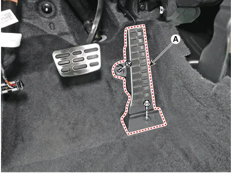
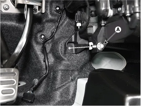
18.Loosen the mounting bolt and nut, remove the accelerator pedal module (A).
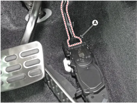
19.Press the lock pin, separate the accelerator pedal connector (A).
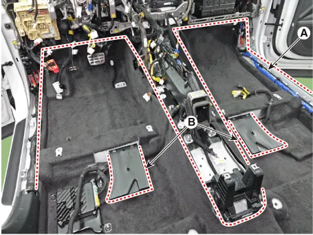
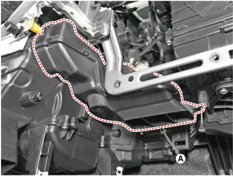
20.Remove the rear air duct (B) and then separate the floor carpet (A) backwards.
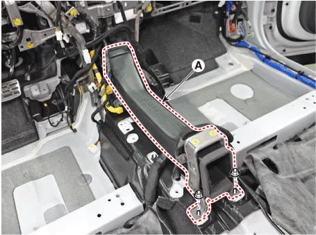
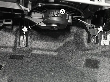
21.Loosen the mounting nuts and remove the rear heating duct (A).
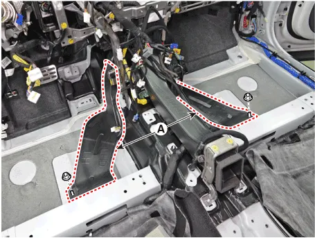
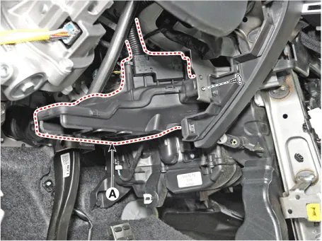
22.Loosen the mounting nuts and remove the console duct (A).
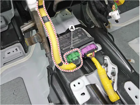
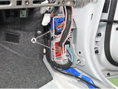
23.Disconnect the airbag control module(SRSCM) connector (A).
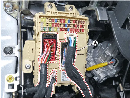
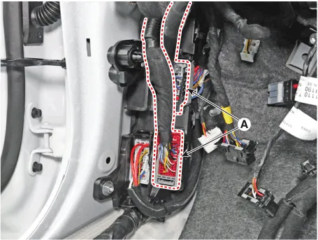
24.Disconnect the passenger compartment junction box connectors (A).
25.Disconnect the multi box connectors (A).
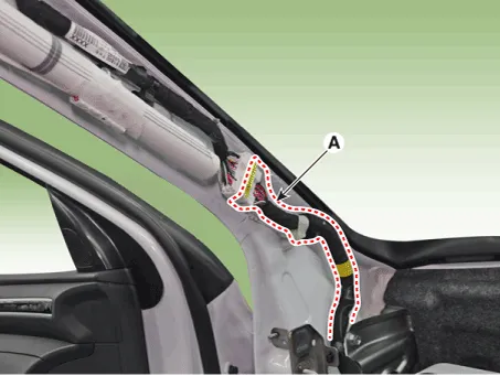
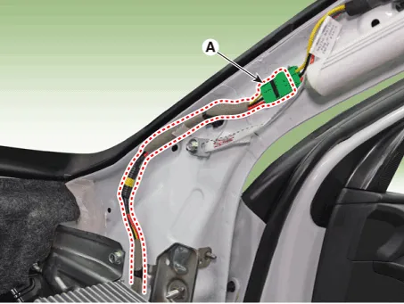
26.Disconnect the connector (A) and the mounting wiring fasteners in the front pillar.
27.Remove the drain hose (A).

28.Remove the lower mounting bolt of the blower unit.
Tightening torque : 3.9 - 5.9 N.m (0.4 - 0.6 kgf.m , 2.9 - 4.3 lb-ft)
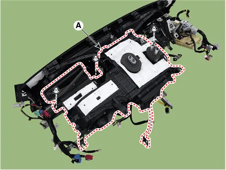
29.After loosening the bolts and nuts remove the crash pad and heater & blower unit assembly (A) together.

30.Remove the DC DC converter.(Refer to Engine Electrical System - "DC DC converter")
31.Remove the IBU.(Refer to Body Electrical System - "Integrated Body Control Unit (IBU)")
32.Remove the heater control unit.(Refer to Controller - "Heater Control Unit")
33.Remove the shower duct.
(1)Loosen the mounting screw, remove the shower duct (A).
(2)Disconnect the PM sesnor connector (A) and hose (B).

(1)Loosen the mounting screw, remove the shower duct (A).
34.Disconnect the heater and blower unit connectors.
(1)Disconnect the PTC heater connector (A).
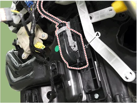
(2)Disconnect the driver's temperature control actuator connector (A).
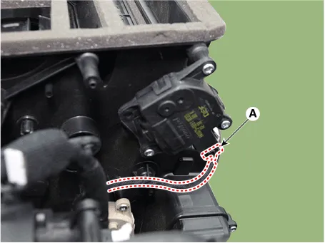
(3)Disconnect the mode control actuator connector (A).
(4)Disconnect the auto defogging actuator connector (A).
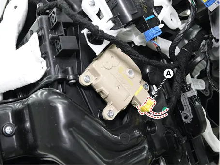
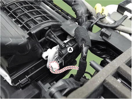
(5)Disconnect the intake actuator connector (A).
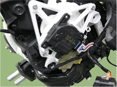
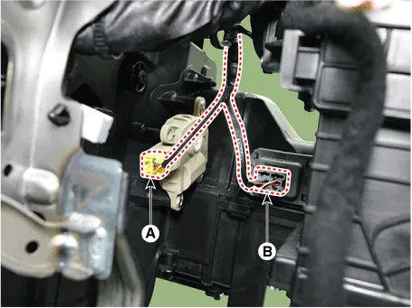
(6)Disconnect the passenger's temperatur actuator connector (A) and power mosfet connector (B).
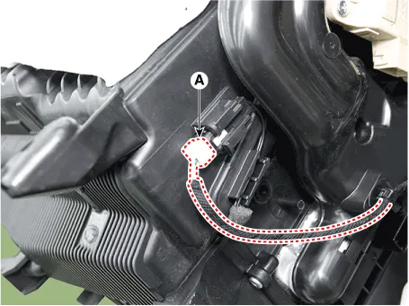
(7)Disconnect the evaporator sensor connector (A).
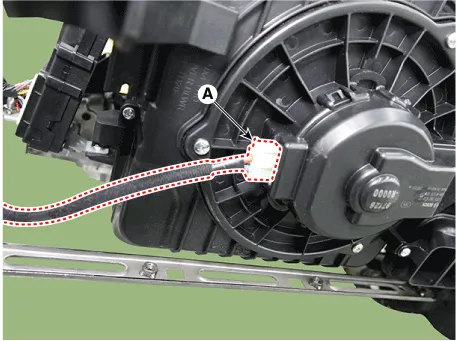
(8)Disconnect the blower motor connector (A).
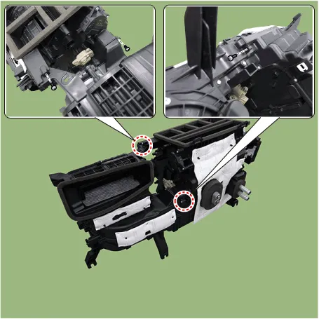
35.Loosen the heater & blower unit mounting bolt (A).
Tightening torque : 3.9 - 5.9 N.m (0.4 - 0.6 kgf.m , 2.9 - 4.3 lb-ft)

36.Loosen the mounting nuts and remove the heater & blower unit (A) from the crash pad.
Tightening torque : 3.9 - 5.9 N.m (0.4 - 0.6 kgf.m , 2.9 - 4.3 lb-ft)
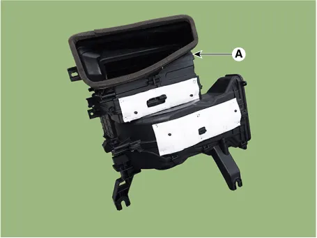
37.Loosen the mounting screw and separate the blower unit (A).
Tightening torque : 3.9 - 5.9 N.m (0.4 - 0.6 kgf.m , 2.9 - 4.3 lb-ft)
38.Install in the reverse order of removal.

• Make sure that each of the assembly components operates properly.
• Replace any damaged clips (or pin-type retainers).
 Blower
...
 Blower Motor
- Inspection
1.Connect the battery voltage and check the blower motor rotation.
2.If the blower motor does not operate well, substitute with a known-good blower motor and check for proper operat ...
Other information:
Hyundai Tucson (NX4) 2022-2025 Owner's Manual: Conditions that Restart the
Engine
The engine is automatically restarted if:
The brake vacuum pressure is low.
The engine has stopped for about 5
minutes.
The air conditioning is ON with the fan
speed set to a certain high level.
The front defroster is ON.
The battery is weak.
The cooling and heating performance
...
Hyundai Tucson (NX4) 2022-2025 Owner's Manual: Starting the Engine
WARNING
Always wear appropriate shoes when
operating your vehicle. Unsuitable
shoes such as high heels, ski boots,
sandals, and flip-flops may interfere
with your ability to use the brake,
accelerator, and clutch pedals. Do not
drive barefoot.
Do not start your vehicle with t ...
