Hyundai Tucson: Charging System / Battery

• After disconnecting then reconnecting the battery negative cable, reset some parts that require the reset procedures. (Refer to Body Electrical System - "General Information")
| Item | Specification |
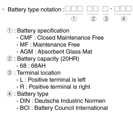
| Model type | CMF68L-DIN |
| Capacity [20HR/5HR] (AH) | 68 / 54 |
| Cold Cranking Amperage (A) | 480 |
| Reserve Capacity (Min) | 110 |
| Specific Gravity | 1.28 [25°C (77°F)] |
| Voltage (V) | 12 |
▷ MF68L-DIN
| Item | Specification |
| Model type | MF68L-DIN |
| Capacity [20HR/5HR] (AH) | 68 / 54 |
| Cold Cranking Amperage (A) | 600 |
| Reserve Capacity (Min) | 110 |
| Specific Gravity | 1.28 [25°C (77°F)] |
| Voltage (V) | 12 |

• Model type description
• Cold Cranking Ampere (CCA) : A rating used in the battery industry to define a battery's ability to start an engine in cold temperatures.
– The rating is the number of amps a new, fully charged battery can deliver at -18°C (-0.4°F) for 30 seconds, while maintaining a voltage of at least 7.2 volts for a 12 volt battery.
– The higher the CCA rating, the greater the starting power of the battery.
• RESERVE CAPACITY (RC) : A battery industry rating, defining a battery's ability to power a vehicle with an inoperative alternator or fan belt.
– The rating is the number of minutes a battery at 26.7°C (80°F) can be discharged at 25 amps and maintain a voltage of 10.5 volts for a 12 volt battery.
– The higher the reserve rating, the longer your vehicle can operate should your alternator or fan belt fail.

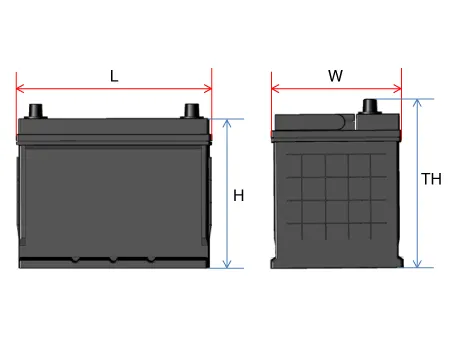
| Capacity (5HR/20HR) | Length | Width | Height | Total Height |
| L (mm) | W (mm) | T (mm) | TH (mm) | |
| 28/35 | 188 - 192 | 126 - 130 | 198 - 202 | 218 - 222 |
| 32/40 | 194 - 198 | 133 - 137 | 199 - 203 | 223 - 227 |
| 36/45 | 203 - 207 | 173 - 177 | 200 - 204 | 221 - 225 |
| 44/55 | 213 - 217 | 173 - 177 | 198 - 202 | 218 - 222 |
| 48/60 | 228 - 232 | 173 - 177 | 200 - 204 | 221 - 225 |
| 54/68 | 258 - 262 | 173 - 177 | 198 - 202 | 220 - 224 |
| 56/70 | 258 - 262 | 173 - 177 | 198 - 202 | 223 - 227 |
| 64/80 | 274 - 278 | 170 - 174 | 198 - 202 | 221 - 225 |
| 70/88 | 349 - 353 | 172 - 176 | 186 - 200 | 183 - 187 |
| 72/90 | 300 - 304 | 170 - 174 | 200 - 204 | 221 - 225 |
| 76/95 | 294 - 298 | 172 - 176 | 198 - 202 | 220 - 224 |
| 80/100 | 326 - 330 | 170 - 174 | 203 - 207 | 225 - 229 |
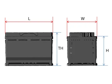
| Capacity (5HR/20HR) | Length | Width | Height | Total Height |
| L (mm) | W (mm) | T (mm) | TH (mm) | |
| 36/45 | 205 - 207 | 173 - 175 | 164 - 168 | 188 - 190 |
| 48/60 | 205 - 207 | 173 - 175 | 164 - 168 | 188 - 190 |
| 54/68 | 205 - 207 | 173 - 175 | 164 - 168 | 188 - 190 |
| 64/80 | 205 - 207 | 173 - 175 | 164 - 168 | 188 - 190 |
| 72/90 | 205 - 207 | 173 - 175 | 164 - 168 | 188 - 190 |
| 80/100 | 205 - 207 | 173 - 175 | 164 - 168 | 188 - 190 |
| 88/110 | 205 - 207 | 173 - 175 | 164 - 168 | 188 - 190 |
| Capacity (5HR/20HR) | Length | Width | Height | Total Height |
| L (mm) | W (mm) | T (mm) | TH (mm) | |
| 40/50 | 205 - 207 | 173 - 175 | 164 - 168 | 188 - 190 |
| 48/60 | 227 - 229 | 173 - 175 | 164 - 168 | 188 - 190 |
| 56/70 | 276 - 278 | 173 - 175 | 164 - 168 | 188 - 190 |
| 64/80 | 312 - 314 | 173 - 175 | 164 - 168 | 188 - 190 |
| 72/90 | 351 - 353 | 173 - 175 | 164 - 168 | 188 - 190 |
| 84/105 | 392 - 394 | 173 - 175 | 164 - 168 | 188 - 190 |
1.Constant current charge: The battery voltage gradually rises by charging with setting a constant current. If charging current and time are not managed correctly, the battery is over-charged, therefore charging should be stopped after confirming the completion of charging.
– General charge: Charging the battery for a long time with low current
– Quick charge: Charging the battery for a short time with high current
2.Constant voltage charge: The battery charge current is gradually reduced by charging with setting a constant voltage.
3.Constant current-Constant voltage charge: Charging with constant current and voltage to protect the battery damage
(1)Initial Stage: Charging with constant current
(2)Last Stage: Charging with constant voltage

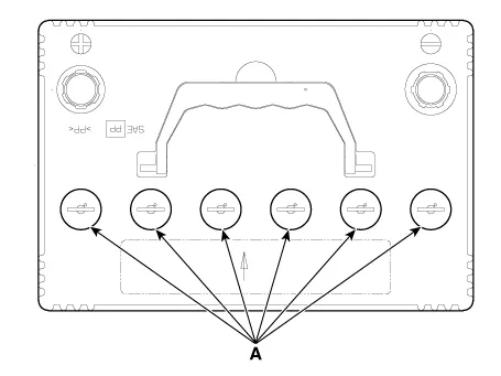
1.Check that the electrolyte level lies between the “UPPER” and the “LOWER” lines.
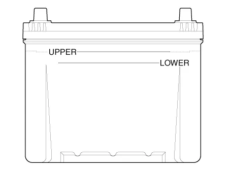
2.If the electrolyte level is below the "LOWER" line, add water until the level of electrolyte comes up to the "UPPER" level.
(1)Remove the cell caps (A) and then carefully add distilled or purified water to bring the level of electrolyte in each cell to the "UPPER" line.
(2)Put the cell caps back on the battery.
(3)Charge the battery to mix the water and residual acid in the battery.

• Never use the water with impurities or additives to fill the battery cells. It will reduce the life and performance of the battery.
• Do not overfill the battery cells. It may result in an "overflow" of the acid electrolyte and cause corrosion on adjacent metal parts, performance deterioration and shortening the life span.
• Make sure the cell caps are installed securely before charging the battery after filling the battery cells.
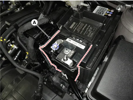
1.Turn the ignition switch OFF and disconnect the battery (-) terminal (A).
Tightening torque :7.8 - 9.8 N.m (0.8 - 1.0 kgf.m, 5.8 - 7.2 Ib-ft)

2.Disconnect the battery (+) terminal (A).
Tightening torque :7.8 - 9.8 N.m (0.8 - 1.0 kgf.m, 5.8 - 7.2 Ib-ft)
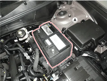
3.Remove the battery mouting bracket (A).
Tightening torque :7.8 - 11.8 N.m (0.8 - 1.2 kgf.m, 5.8 - 8.7 Ib-ft)

4.Remove the battery (A).
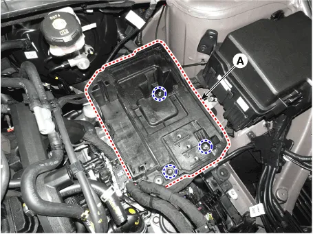
1.Remove the battery.
2.Remove the air cleaner assembly.(Refer to Engine Mechanical System - "Air Cleaner")
3.Remove the engine control module (ECM).(Refer to Engine Control / Fuel System - "Engine Control Module (ECM)")
4.Remove the battery tray (A).
Tightening torque :7.8 - 10.8 N.m (0.8 - 1.1 kgf.m, 5.8 - 8.0 Ib-ft)
1.Install in the reverse order of removal.

• When installing the battery, fix the mounting bracket on the tray correctly.

• After disconnecting then reconnecting the battery negative cable, reset some parts that require the reset procedures. (Refer to Body Electrical System - "General Information")
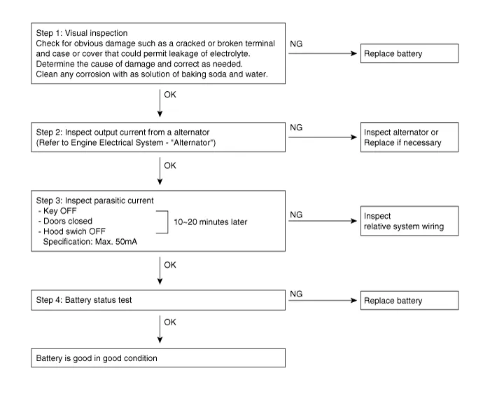
1.Turn the all electric devices OFF, and then turn the ignition switch OFF.
2.Close all doors except the engine hood, and then lock all doors.
(1)Disconnect the hood switch connector.
(2)Close the trunk lid.
(3)Close the doors or remove the door switches.
3.Wait a few minutes until the vehicle’s electrical systems go to sleep mode.

• For an accurate measurement of a vehicle parasitic current, all electrical systems should go to sleep mode. (It takes at least one hour or at most one day.) However, an approximate vehicle parasitic current can be measured after 10 - 20 minutes.
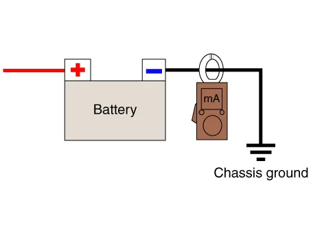
4.Connect an ammeter in series between the battery (-) terminal and the ground cable, and then disconnect the clamp from the battery (-) terminal slowly.

• Be careful that the lead wires of an ammeter do not come off from the battery (-) terminal and the ground cable to prevent the battery from being reset. In case the battery is reset, connect the battery cable again, and then start the engine or turn the ignition switch ON for more than 10 sec. Repeat the procedure from No. 1.To prevent the battery from being reset during the inspection,
1)Connect a jump cable between the battery (-) terminal and the ground cable.
2)Disconnect the ground cable from the battery (-) terminal.
3)Connect an ammeter between the battery (-) terminal and the ground cable.
4)After disconnecting the jump cable, read the current value of the ammeter.
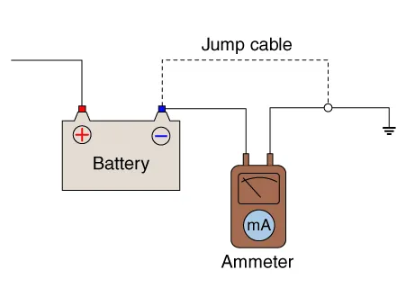
5.Read the current value of the ammeter.
• If the parasitic current is over the limit value, search for abnormal circuit by removing a fuse one by one and checking the parasitic current.
• Reconnect the suspected parasitic currentdraw circuit fuse only and search for suspectedunit by removing the component connected with thecircuit one by one until the parasitic draw dropsbelow limit value.
Limit value (after 10 - 20 min.) : Below 50 mA
1.Turn the all electric devices OFF, and then turn the ignition switch OFF.
2.Close all doors except the engine hood, and then lock all doors.
(1)Disconnect the hood switch connector.
(2)Close the trunk lid.
(3)Close the doors or remove the door switches.
3.Wait a few minutes until the vehicle’s electrical systems go to sleep mode.

• For an accurate measurement of a vehicle parasitic current, all electrical systems should go to sleep mode. (It takes at least one hour or at most one day.) However, an approximate vehicle parasitic current can be measured after 10 - 20 minutes.
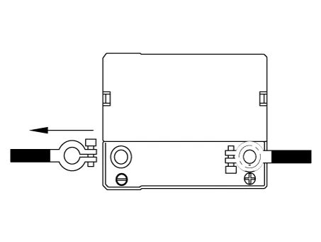
4.Install the clamp type ammerter on battery negative (-) terminal.
5.Read the current value of the ammeter.
• If the parasitic current is over the limit value, search for abnormal circuit by removing a fuse one by one and checking the parasitic current.
• Reconnect the suspected parasitic currentdraw circuit fuse only and search for suspectedunit by removing the component connected with thecircuit one by one until the parasitic draw dropsbelow limit value.
Limit value (after 10 - 20 min.) : Below 50 mA
1.Connect the diagnostic device (GDS) to the connector under the crash pad of the driver seat.
2.Perform "Battery Diagnosis" procedure with diagnostic tool.(S/W Management → Integrated Central Control Unit → Battery diagnosis)
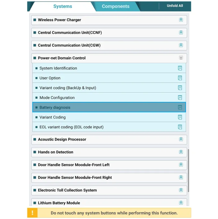
3.Take measure according to the diagnosis result.※ Battery diagnosis result statement
| Item | Code | |
| Replace | Internal defect | R01 |
| Aging | R02 | |
| Discharge | Excess dark current | D01 |
| Aftermarket electronic device | D02 | |
| Excess use | D03 | |
| Lack of driving | D04 | |
| Normal | D00 | |
1.Make sure that the ignition switch and all accessories are in the OFF position.
2.Disconnect the battery cables (negative first).
3.Remove the battery from the vehicle.

• Care should be taken in the event the battery case is cracked or leaking, to protect your skin from the electrolyte.Heavy rubber gloves (not the household type) should be wore when removing the battery.
4.Inspect the battery tray for damage caused by the loss of electrolyte. If acid damage is present, it will be necessary to clean the area with a solution of clean warm water and baking soda. Scrub the area with a stiff brush and wipe off with a cloth moistened with baking soda and water.
5.Clean the top of the battery with the same solution as described above.
6.Inspect the battery case and cover for cracks. If cracks are present, the battery must be replaced.
7.Clean the battery posts with a suitable battery post tool.
8.Clean the inside surface of the terminal clamps with a suitable battery cleaning tool. Replace damaged or frayed cables and broken terminal clamps.
9.Install the battery in the vehicle.
10.Connect the cable terminals to the battery post, making sure tops of the terminals are flush with the tops of the posts .
11.Tighten the terminal nuts securely.
12.Coat all connections with light mineral grease after tightening.

• When batteries are being charged, an explosive gas forms beneath the cover of each cell. Do not smoke near batteries being charged or which have recently been charged. Do not break live circuit at the terminals of batteries being charged.A spark will occur when the circuit is broken. Keep open flames away from battery.
 Alternator
- Description
The Alternator has eight built-in diodes, each rectifying AC current to
DC current.Therefore, DC current appears at alternator "B" terminal.In
addition, the charging voltage of th ...
 Battery Sensor
- Description
Vehicles have many control units that use more electricity. These units
control their own system based on information from various sensors. It
is important to provide a stable pow ...
Other information:
Hyundai Tucson (NX4) 2022-2025 Owner's Manual: Reverse Parking Collision-
Avoidance Assist Malfunction
and Limitations
Reverse Parking Collision-
Avoidance Assist malfunction
When Reverse Parking Collision-
Avoidance Assist or other related
functions are not working properly,
the "Check Parking Safety system"
warning message may appear on the
instrument cluster, and Reverse Parking
Collision-Avoidan ...
Hyundai Tucson (NX4) 2022-2025 Owner's Manual: Maintenance When Towing a
Trailer
Your vehicle needs servicing more
often when you regularly pull a trailer.
Important items to pay particular
attention to include engine oil,
transmission fluid, axle lubricant, and
cooling system fluid. Brake condition
is another important item to frequently
check. If you are traileri ...
