Hyundai Tucson: AVN System / AVN Head Unit
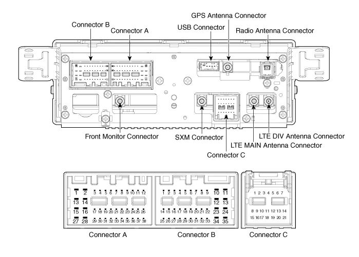
| No | Connector A (ExternalAmplifier) | Connector A (Internal Amplifier) | Connector B | Connector C |
| 1 | - | Rear door speaker LH (+) | Mic2 (+) | - |
| 2 | - | Rear door speaker LH (-) | Mic1 (+) | I -CAN (High) |
| 3 | Navigation voice (+) | - | - | - |
| 4 | External amplifier SPDIF (+) | - | - | - |
| 5 | Reset | Reset | - | - |
| 6 | Camera power | Camera power | Illumination (+) | - |
| 7 | Camera video | Camera video | M-CAN (High) | - |
| 8 | - | - | - | - |
| 9 | - | - | - | I -CAN (Low) |
| 10 | - | - | Battery (+) | - |
| 11 | DETECT | DETECT | Battery (+) | - |
| 12 | Steering wheel remote | Steering wheel remote | Ground | - |
| 13 | - | Front door speaker LH (+) | Ground | - |
| 14 | - | Front door speaker LH (-) | Mic2 (-) | - |
| 15 | - | Front door speaker RH (-) | Mic1 (-) | - |
| 16 | - | Front door speaker RH (+) | - | MTS |
| 17 | Navigation voice (-) | - | - | - |
| 18 | External amplifier SPDIF (-) | - | - | - |
| 19 | External amplifier SPDIF (Ground) | - | Illumination (-) | - |
| 20 | Camera power ground | Camera power ground | M-CAN (Low) | - |
| 21 | Camera video ground | Camera video ground | - | - |
| 22 | - | - | ACC | |
| 23 | - | - | Keyboard power | |
| 24 | - | - | Front monitor power | |
| 25 | - | - | - | |
| 26 | Steering wheel remote ground | Steering wheel remote ground | - | |
| 27 | - | Rear door speaker RH (-) | - | |
| 28 | - | Rear door speaker RH (+) | - | |
| 29 | - | - | - | |
| 30 | - | - | - | |
| 31 | - | - | - | |
| 32 | Camera Detect (RVM : - / SVM : Ground) | Camera Detect (RVM : - / SVM : Ground) | - | |
| 33 | Camera shield ground | Camera video shield | IGN 1 | |
| 34 | - | - | Keyboard ground | |
| 35 | - | - | Front motor ground | |
| 36 | - | - | ||
| 37 | - | - | ||
| 38 | Vehicle speed | Vehicle speed |
1.Disconnect the negative (-) battery terminal.
2.Remove the front monitor lower cover (A).
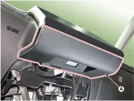
3.Remove the front monitor lower cover after disconnecting the mood lamp connector (A).
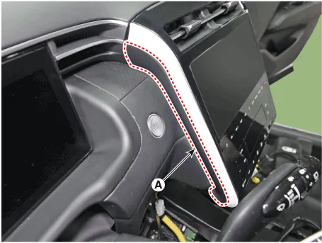
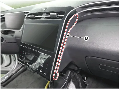
4.Remove front monitor side cover (A) and (B).
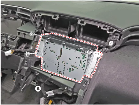
5.Remove the front monitor assembly (A).
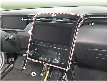
6.Remove the front monitor assembly (A) after disconnecting monitor connectors.
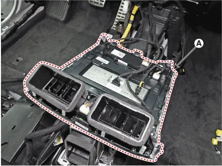
7.Remove the AVN head unit after loosening mounting screws.
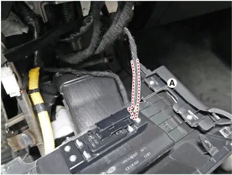
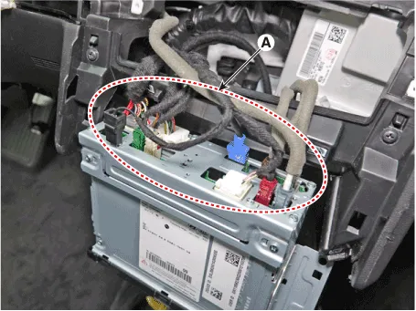
8.Remove the AVN head unit after disconnect audio connectors (A).
1.Install AVN head unit connectors and antenna connectors.
2.Install the AVN head unit.
3.Install the front monitor assembly.
4.Install the front monitor side cover.
5.Install the front monitor lower cover.
6.Connect the negative (-) battery terminal.

• Make sure the connector are connected in properly.
• Check the AVN system for normal operation. (navigation, radio, USB, bluetooth)
 Specifications
- Specifications
ItemSpecification
Power sourceDC 14.4V (-) ground
Frequency range / Channel spaceFM : 87.5 - 108.0 MHz / 100 KHzAM : 531 - 1602 KHz / 9 KHz
Tuning typePLL SYNTHESIZED TUNING
Im ...
 External Amplifier
- Components
Connector Pin Information
NoConnector AConnector B
1Battery (+)Front right door tweeter speaker (+)
2Battery (+)Front left door tweeter speaker (+)
3Battery (+)Sub woofer speake ...
Other information:
Hyundai Tucson (NX4) 2022-2025 Service Manual: Surround View Monitor (SVM) Camera
- Components
[Ultra Optical Camera - RH/LH]
[Ultra Optical Camera - Front]
[Ultra Optical Camera - Rear]
- Removal
• In case of bad quality or poor focus, be sure to check the camera lense surface condition and foreign materials.
SVM Front Camera
1.Discon ...
Hyundai Tucson (NX4) 2022-2025 Owner's Manual: Recommended Lubricants and Capacities
To help achieve proper engine and powertrain performance and durability, use
only
lubricants of the proper quality. The correct lubricants also help promote the
engine
efficiency that results in improved fuel economy.
These lubricants and fluids are recommended for use in your vehicle.
N ...
